
User's Manual

9
FINAL.Not for distribution.
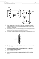
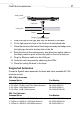
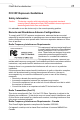
5. Snap the clips of the light pipe into the bottom of the case.
6. Fit the light pipe into hole in the tile from its unfinished side.
7. Place the decal on the back of the badge and snap the badge onto
the light pipe from the finished side of the tile.
8. Bring the tile into the ceiling space, and attach any safety cable to
the safety cable tie point or security cable to the unit’s lock port.
9. Plug the Ethernet cable into the LAN port.
10. Verify the unit has power by observing the LEDs.
11. Place the ceiling tile back in its frame.
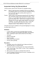
Supported Antennas
Contact a Symbol sales associate for these and other available AP 300
antenna options.
802.11b/g Antennas
802.11a Antennas
Antenna Option Part Number
2.4-2.5Ghz, 11 dBi 120 Degree Sector Antenna ML-2499-11PNA2-01
2.4-2.5Ghz, 3.5 dBi Fixed Point Dipole Antenna ML-2499-APA2-01
2.4-2.5Ghz, 5 dBi OMNI Antenna ML-2499-HPA3-01
2.4-2.5Ghz, 14 dBi YAGI Antenna ML-2499-BYGA2-01
Antenna Option Part Number
5.15GHz to 5.825GHz, 2Bi RSMA Dipole Antenna ML-5299-APA1-01
5.15GHz to 5.825GHz, 13Bi Patch Antenna ML-5299-WPNA1-01
5.15GHz to 5.825GHz, 5Bi OMNI Antenna ML-5299-HPA1-01
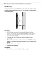
Badge
Decal
Ceiling Tile
Light Pipe
Safety Cable