
User's Manual
Installation Instructions
The AP 300 Access Port mounts either on a wall with mounting screws or in the ceiling.
To prepare for installation, perform the following steps:
1. Match the model number on the purchase order with the model numbers in the packing
list and on the case of the device shipped.
2. Verify that the contents of the box include the intended AP 300 Access Port and
mounting hardware:
3. Review site survey and network analysis reports to determine the location and
mounting position for the AP 300 Access Port.
4. Connect a CAT-5 cable to a compatible 802.3af power source and run the cable to the
installation site. Ensure that there is sufficient slack on the cable to perform the
installation steps.
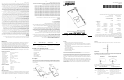
Wall Mount
Wall mounting requires hanging the AP 300 Access Port along its width or length using the pair
of slots on the bottom of the unit. The AP 300 can be mounted onto any plaster, wood, or
cement wall surface using the provided wall anchors when necessary. The illustration shows a
lengthwise mount.
Item Notes
WSAP-5100-100-WW 802.11a and 802.11b/g configurations with external RSMA (.11a radio)
and RBNC (.11g radio) antenna connectors. The antenna is a separate
purchasable item.
Mounting Hardware: Two Phillips pan head self-tapping screws.
Wall Mount Hardware
• Two Phillips pan head self-tapping screws
• Two wall anchors
• Safety wire (recommended) and security cable (optional)
Note: In the event that the original mounting screws are lost, the following screws
can be used instead:(ANSI Standard) #6-18 X 0.875in. Type A or AB Self-Tapping
Screw, or (ANSI Standard Metric) M3.5 X 0.6 X 20mm Type D Self-Tapping
Screw
Wall Mount Procedure
1. Orient the case on the wall by its width or length.
2. Using the arrows on one edge of the case as guides,
move the edge to the midline of the mounting area and mark points on the midline for
the screws.
3. At each point, drill a hole in the wall, insert an anchor, screw into the anchor the wall
mounting screw and stop when there is 1mm between the screw head and the wall.
Note: When pre-drilling a hole the recommended hole size is 2.8mm (0.11in.) if the
screws are going directly into the wall and 6mm (0.23in.) if the provided wall
anchors are being used.
4. If required, loop a safety wire, between .15cm (.06in.) and .25cm (.10in.) in diameter,
around the tie post and secure the loop.
5. If required, install and attach a security cable to the unit’s lock port.
6. Place the large corner of each of the case’s mount slots over the screw heads.
7. Slide the case down along the mounting surface to hang the mount slots on the screw
heads.
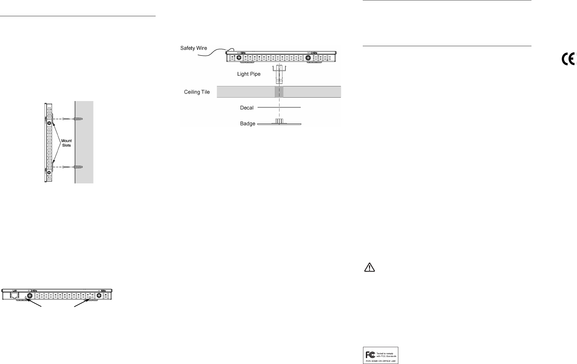
8. Attach appropriate antennas to the connectors.
9. Attach the Ethernet cable to the unit and to a switch with an 802.3af compatible power
source.
10. Verify the unit has power by observing that the LEDs are lit or flashing.
Alignment Arrows
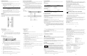
Suspended Ceiling Tile (Plenum) Mount
Ceiling mount requires placing the AP 300 Access Port above a suspended ceiling and installing
the provided light pipe for viewing the status lights of the unit.
Note:Notes or warnings about suspended ceiling mounts apply to all installations where
the unit is placed on suspended ceiling tile. The case has a safety wire tie point for
a standard safety wire.
Caution: Symbol does not recommend mounting the AP 300 Access Port directly to any
suspended ceiling tile with a thickness less than 1.27cm (0.5in.) or a suspended
ceiling tile with an unsupported span greater than 66cm (26in.). Symbol does strongly
recommend fitting the AP 300 Access Port with a safety wire suitable for the specific
installation. The safety wire should be a standard ceiling suspension cable or
equivalent steel wire between .159cm (.062in.) and .25cm (.10in.) in diameter.
This placement requires installation of the provided light pipe for viewing the status lights of
the unit.
Ceiling Mount Hardware
• Light pipe
• Badge for light pipe
• Decal for badge
• Safety wire (recommended) and security cable (optional)
Ceiling Mount Procedure
1. If possible, remove the ceiling tile from its frame and place it, finished side down, on a work
surface.
2. If required, install a safety wire, between .15cm (.06in.) and .25cm (.10in.) in diameter, in
the ceiling space.
3. If required, install and attach a security cable to the unit’s lock port.
4. Mark a point on the upper or unfinished side of the tile.
5. Push the light pipe through the tile at the mark and remove the light pipe. If necessary, use
a drill to make a hole in the tile.
6. Snap the clips of the light pipe into the bottom of the case.
7. Fit the light pipe into hole in the tile from its unfinished side.
8. Place the decal on the back of the badge and snap the badge onto the light pipe from the
finished side of the tile.
9. Attach appropriate antennas to the connectors.
10. Attach any safety wire to the safety wire tie point or security cable to the unit’s lock port.
11. Bring the tile into the ceiling space.
12. Plug the Ethernet cable into the the unit and to a switch with an 802.3af-compatible power
source.
13. Verify the unit has power by observing the LEDs.
14. Place the ceiling tile back in its frame.
Supported Antennas
Contact a Symbol sales associate for these and other available AP 300 Access Port antenna
options.
802.11b/g Antennas
802.11a Antennas
Regulatory Information
All Symbol devices are designed to be compliant with rules and regulations in locations they are
sold and will be labeled as required. Any changes or modifications to Symbol Technologies
equipment, not expressly approved by Symbol Technologies, could void the user’s authority to
operate the equipment.
Use only the approved antennas. Unauthorized antennas, modifications, or attachments could
cause damage and may violate regulations.
This device is to be used only with Symbol Technologies Wireless Switch.
Country Approvals
Regulatory markings are applied to the device signifying the radio (s) are approved for use in the
following countries: United States, Canada, Australia, Japan & Europe 1,2. Please refer to the
Symbol Declaration of Conformity (DoC) for details of other country markings. This is available at
http://www2.symbol.com/doc/.
Note 1: For 2.4GHz Products: Europe includes, Austria, Belgium, Croatia, Czech Republic, Croat-
ia, Cyprus, Denmark, Estonia, Finland, France, Germany, Greece, Hungary, Iceland, Ire-
land, Italy, Latvia, Liechtenstein, Lithuania, Luxembourg, Malta, Netherlands, Norway,
Poland, Portugal, Slovak Republic, Slovenia, Spain, Sweden, Switzerland, and the Unit-
ed Kingdom.
Antenna Option Part Number
2.4-2.5Ghz, 11.2dBi 120 Degree Sector Antenna ML-2499-11PNA2-01
2.4-2.5Ghz, 2dBi Fixed Point Dipole Antenna ML-2499-APA2-01
2.4-2.5Ghz, 4.6dBi OMNI Antenna ML-2499-HPA3-01
2.4-2.5Ghz, 14.2dBi YAGI Antenna ML-2499-BYGA2-01
Antenna Option Part Number
4.9GHz to 5.825GHz, 2dBi RSMA Dipole Antenna ML-5299-APA1-01
4.9GHz to 5.825GHz, 14.2dBi Patch Antenna ML-5299-WPNA1-01
4.9GHz to 5.825GHz, 5.9dBi OMNI Antenna ML-5299-HPA1-01
Note 2: The use of 5GHz RLAN’s has varying restrictions of use; please refer to the Symbol Dec-
laration of Conformity (DoC) for details.
Operation of the device without regulatory approval is illegal.
Frequency of Operation
The use on UNII (Unlicensed National Information Infrastructure) Band 1 5150-5250 MHz is restricted to indoor
use only.
FCC/EU RF Exposure Guidelines
Safety Information
The device complies with Internationally recognised standards covering Specific Absorption Rate
(SAR) related to human exposure to electromagnetic fields from radio devices. It is advisable to
use the device only in the normal operating position.
Remote and Standalone Antenna Configurations
To comply with FCC RF exposure requirements, antennas that are mounted externally at remote
locations or operating near users at stand-alone desktop or similar configurations must operate
with a minimum separation distance of 20 cm from all persons.
Power Supply
This device is powered from a 802.3af compliant power source which is UL approved.
Radio Frequency Interference Requirements
This equipment has been tested and found to comply with the limits for a
Class B digital device, pursuant to Part 15 of the FCC rules. These limits are
designed to provide reasonable protection against harmful interference in a
residential installation. This equipment generates, uses and can radiate
radio frequency energy and, if not installed and used in accordance with the instructions, may
cause harmful interference to radio communications. However there is no guarantee that
interference will not occur in a particular installation. If this equipment does cause harmful
interference to radio or television reception, which can be determined by turning the equipment
off and on, the user is encouraged to try to correct the interference by one or more of the following
measures:
• Reorient or relocate the receiving antenna
• Increase the separation between the equipment and receiver
• Connect the equipment into an outlet on a circuit different from that to which the receiver is
connected
• Consult the dealer or an experienced radio/TV technician for help.
Radio Transmitters (Part 15)
This device complies with Part 15 of the FCC Rules. Operation is subject to the following two
conditions: (1) this device may not cause harmful interference, and (2) this device must accept
any interference received, including interference that may cause undesired operation.
Radio Frequency Interference Requirements – Canada
This Class B digital apparatus complies with Canadian ICES-003.
Cet appareil numérique de la classe B est conforme à la norme NMB-003 du Canada.
Radio Transmitters
This device complies with RSS 210 of Industry & Science Canada. Operation is subject to the
following two conditions: (1) this device may not cause harmful interference and (2) this device
must accept any interference received, including interference that may cause undesired
operation.
Label Marking: The Term “IC:” before the radio certification only signifies that Industry Canada
technical specifications were met.
CE Marking and European Economic Area (EEA)
The use of 2.4GHz RLAN’s, for use through the EEA, have the following restrictions:
• Maximum radiated transmit power of 100 mW EIRP in the frequency range 2.400 -2.4835
GHz
• France, outside usage is restricted to 2.4-2.454 GHz
• Belgium, outside usage is restricted to 2.460-2.4835 GHz
• Italy requires a user license for outside usage.
The use of 5GHz RLAN’s has varying restrictions for use within the EEA; please refer to the
Symbol Declaration of Conformity (DoC) for details at http://www2.symbol.com/doc/
Statement of Compliance
Symbol Technologies, Inc., hereby, declares that this device is in compliance with the essential
requirements and other relevant provisions of Directive 1999/5/EC. A Declaration of
Conformity may be obtained from
http://www2.symbol.com/doc/
Other Countries
Mexico - Restrict Frequency Range to: 2.450 - 2.4835 GHz.
Sri Lanka - Restrict Frequency Range to: 2.400 – 2.430 GHz.
Customer Support
Symbol Technologies provides its customers with prompt and accurate customer support. Use
the Symbol Support Center as the primary contact for any technical problem, question or
support issue involving Symbol products.
If the Symbol Customer Support specialists cannot solve a problem, access to all technical
disciplines within Symbol becomes available for further assistance and support. Symbol
Customer Support responds to calls by e-mail, telephone or fax within the time limits set forth
individual contractual agreements.
When contacting Symbol Customer Support, please provide the following information:
• Device serial number
• Product name or model number
• Software type and version number
For warranty and service information, contact the Symbol Support Center: telephone 1-631-
738-6213 or 1-800-653-5350; fax: (631) 563-5410; or E-mail: support@symbol.com.
Web Support Sites and Additional Information
Obtain additional information by contacting Symbol at:
• 1-800-722-6234, inside North America
• +1-631-738-5200, in/outside North America
• http://www.symbol.com/
North American Contacts International Contacts
Inside North America, contact Symbol at:
Outside North America, contact Symbol at:
Symbol Technologies, Inc.
Symbol Technologies, Inc.
One Symbol Plaza
Symbol Place
Holtsville, New York 11742-1300
Winnersh Triangle, Berkshire, RG41 5TP
United Kingdom
1-631-738-2400/1-800-SCAN 234
0800-328-2424 (Inside UK) /+44 118 945 7529 (Outside UK)
Fax: 1-631-738-5990
MySymbolCare http://www.symbol.com/services/msc/
Symbol Services Homepage http://symbol.com/services/
Symbol Software Updates http://symbol.com/services/downloads/
Symbol Developer Program http://software.symbol.com/devzone/
Symbol Knowledge Base http://kb.symbol.com/register.asp
(14)(12)(10)(8)
(7) (9) (11) (13)