Symbol IEEE 802.
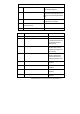
To The Installer ................................................................................................................................4 Purpose .......................................................................................................................................4 Document Conventions................................................................................................................4 Warnings:.............................................................................
If the appropriate stamp(s)is not provided, please contact your supplier..... 19 To apply the country stamp:.................................................................................................. 19 FCC RF Exposure Guidelines ....................................................................................... 20 Safety Information .....................................................................................................................
To the Installer This guide is intended for the technician responsible for installing Symbol Technologies IEEE 802.11a Access Port. It is assumed that the technician is familiar with Ethernet LAN-based networking, terms and concepts. The installing technician should also have a working knowledge of mechanical assembly as well as an understanding of local building codes. Purpose The purpose of this document is to provide specifications, features and guidelines for the installer to use during installation.
Introduction The 5030 Access Port provides area coverage to 802.11a/b (when configured with 802.11a/b radios) wireless network devices. The Access Port includes different placement options, allowing best placement for it to operate within its optimum range. The standard mounting base allows the unit to be secured to a wall by the use of two screws and wall anchors (included, use if needed). Use the mounting bracket as a template for marking the location of the mounting holes.
Radio Characteristics The Access Port can be configured as an IEEE 802.11 a/b compliant device. As an IEEE 802.11a device it supports 6, 9, 12, 18, 24,36, 48 and 54 Mbps data rates, utilizing transmit-only diversity, in the 5.15 to 5.825 GHz range. As an IEEE 802.11b device it supports 1.0, 2.0, 5.5 and 11.0 Mbps data rates, utilizing transmit and receive diversity, in the 2.4 to 2.5 GHz ISM radio band.
Overview The WSAP 5030-xxx-WW system is available in an 802.11a, 802.11b or 802.11a/b radio configuration. Configurations include internal antennas or external antenna connectors. External antennas are optional (see add-on options addendum for installation of options). Verify model number of purchase order matches the packing list model number and the device model number in the box.
Display of AP exploded view and wall mounting hardware identified by item numbers. Caution! Symbol does not recommend mounting the Access Port directly (above or below) to any suspended ceiling tile with a thickness less than ½ an inch or a suspended ceiling tile with an unsupported span greater than 26 inches. Symbol recommends that the Access Port be fitted with a customer supplied Safety Cable suitable for the specific installation. The safety cable should be steel at least .06 - .
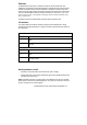
Mounting Hardware Wall, Desk 2. Rubber feet (4) Apply to bottom of Access Port only on desk mounted installations 3. Metal mounting bracket Below ceiling and wall bracket are the same. Bracket is packaged with Access Port and not with mounting kit hardware items. 4. # 10 wall screws (2) Sheet metal self-tapping for use with provided anchors (if needed). 5. # 10 wall anchors (2) 6. Installation Guide Item number Item Notes Ceiling Mounting Hardware Metal mounting bracket Same as wall bracket.
installation Light Pipe Decal 14. For use with above ceiling installation. Display of AP exploded view and ceiling mounting hardware identified by item number. Review Site survey and network analysis reports to determine the method for Access Port installation.
Surface Mounting 802.11a/b Access Ports mount to most vertical or horizontal surfaces using the surface mounting hardware provided. Use the mounting bracket as a template to determine the proper placement for the unit and the mounting screws. Display of AP, wall mounting hardware, and identified cable connectors (LAN/ACC). Display wall mounting metal bracket in a horizontal position with open (raised) part of the mounting snap towards the floor. Wall Mounting 1.
Note: Use only CAT 5 Ethernet cable without molded or integrated strain relief on the connector that interfaces with an Access Port. If a similar Access Port is daisy chained connect the Ethernet cable from the ACC port to the LAN port on the daisy chained device. Plaster Wall Board Ceiling Mount 1. Use the metal mounting bracket as a template to install the metal bracket in a horizontal orientation with the open (raised) part of the mounting “snap” facing away from the installer.
Above Suspended Ceiling Tile (Plenum) Mount 1. Place the plastic mounting bracket flat against the ceiling tile when marking the mounting holes. 2. Use the mounting bracket as a template to mark the locations of the two mounting holes and the light pipe (the large hole in the center of the bracket) on the ceiling tile. 3. Use the screws to tap the holes at the locations marked and cut out the marked location of the light pipe. 4. Install a screw and washer in each hole below the ceiling tile. 5.
Below Suspended Ceiling (T-Bar) Mount Display AP Ethernet cable/power connection. Ceiling mount H/W, Ceiling tile, Ceiling mount light pipe, Ceiling mount badge 1. Determine the suspended (below) ceiling mounting location of the Access Port. 2. Loosely assemble the two clip halves by holding the clip halves facing each other clip side up (place the long channel section of one clip half on top of the other) so they form a “U” shape. 3.
Note: Use the rubber feet provided for desk mount installations only Use only CAT 5 Ethernet cable without molded or integrated strain relief on the connector that interfaces with an Access Port. If a similar Access Port is daisy chained connect the Ethernet cable from the ACC port to the LAN port on the daisy chained device. The Access Port receives power from an Ethernet cable or from a Symbol approved power supply. It supports the following Symbol-branded Power-Over-Ethernet devices and power supply.
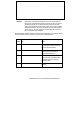
Available Options Contact a Symbol sales associate for available Access Port radio and antenna options. Radio or Antenna Option Part number Notes Internal .11a antenna WSM-5040-110-WW Requires a special removal/installation tool. Not supplied by Symbol Technologies. External RSMA .11a Dipole antenna ML-5299-APA1-01 11b radio w/external antenna connectors WSM-5030-200-WW Requires a special removal/installation tool. Not supplied by Symbol Technologies. Internal .
Customer Support Symbol Technologies provides its customers with prompt and accurate customer support. Use the Symbol Support Center as the primary contact for any technical problem, question or support issue involving Symbol products. If the Symbol Customer Support specialists cannot solve a problem, access to all technical disciplines within Symbol becomes available for further assistance and support.
Obtain additional information by contacting Symbol at: • 1-800-722-6234, inside North America • +1-516-738-5200, in/outside North America • http://www.symbol.
Legal Information Regulatory Information All Symbol devices are designed to be compliant with rules and regulations in locations they are sold and will be labeled as required. Any changes or modifications to Symbol Technologies equipment, not expressly approved by Symbol Technologies, could void the user’s authority to operate the equipment. Antenna’s, use only the supplied or an approved replacement antenna.
FCC RF Exposure Guidelines Safety Information The device complies with internationally recognized standards covering Specific Absorption Rate (SAR) related to human exposure to electromagnetic fields from radio devices. It is advisable to use the device only in the normal operating position and it is recomended that no part of the human body be allowed to come too close to the antenna during operation of the equipment. Remote and Standalone Antenna Configurations.
Radio Frequency Interference Requirements This equipment has been tested and found to comply with the limits for a Class B digital device, pursuant to Part 15 of the FCC rules. These limits are designed to provide reasonable protection against harmful interference in a residential installation. This equipment generates, uses and can radiate radio frequency energy and, if not installed and used in accordance with the instructions, may cause harmful interference to radio communications.
Radio Frequency Interference Requirements – Canada This device complies with RSS 210 of Industry & Science Canada. Operation is subject to the following two conditions: (1) this device may not cause harmful interference and (2) this device must accept any interference received, including interference that may cause undesired operation. This Class B digital apparatus complies with Canadian ICES-003. Cet appareil numérique de la classe B est conforme à la norme NMB-003 du Canada.
Other Countries Mexico - Restrict Frequency Range to: 2.450 - 2.4835 GHz. Israel - Restrict Frequency Range to: 2.418 – 2.457 GHz. Sri Lanka- Restrict Frequency Range to: 2.400 – 2.430 GHz.
Copyright Copyright © 2003 by Symbol Technologies, Inc. All rights reserved. No part of this publication may be modified or adapted in any way, for any purposes without permission in writing from Symbol Technologies, Inc. (Symbol). The material in this manual is subject to change without notice. Symbol reserves the right to make changes to any product to improve reliability, function, or design.
Telex: 6711519 http://www.symbol.