
Quick Reference Guide
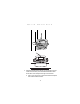
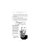
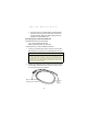

Table Of Contents

15
Quick Reference
b. Route the External DC power cable from the terminal lo-
cation to the connection point for your vehicle’s power
source.
c. Prepare the cable termination: Strip 3/8” of insulation
from the two wire ends and terminate them with a con-
nector that matches your vehicle’s requirements. See the
Installation Note below.
Connect the red wire to the vehicle power source. Con-
nect the black wire to a vehicle ground wire or chassis
ground.
d. Connect the External DC power cable to your vehicle
power source.
3. Insert the terminal end of the External DC power cable into
the terminal’s Power Connector. Align the red dot on the end
of the power cable with the red dot on the Power Connector.
Installation Note: Cable Routing Caution
The means of routing and securing the External DC power cable from
the terminal to the vehicle power source is extremely important. Haz-
ards associated with improper wiring can be severe.
To avoid unintentional contact between the wire and any sharp edges,
provide the cable with proper bushings and clamping where it passes
through openings. If the wire is subjected to sharp surfaces and excess
engine vibration, the wiring harness insulation can wear away, causing
a short between the bare wire and chassis. This can start a fire.
Installation Note: Cable Termination
How the cable terminates depends on your vehicle. If your vehicle has
a power output connector, then attach a mating connector to the end
of the power cable. You may be able to connect to a fuse panel with a
commercially available connector. If your vehicle has no power output
connector, attach a ring terminal (for a battery post) or blade terminal
connector (for a fuse panel).
Consult your vehicle Owner’s Manual for information on how to access
your vehicle’s power supply.
! !