
User's Manual
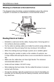
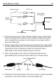
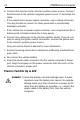
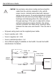
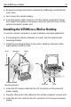
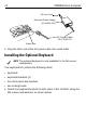
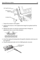
Table Of Contents
- Warranty
- Patents
- Introduction
- About This Guide
- Features
- Unpacking
- Optional Accessories
- Mounting Bracket Installation
- Installing the Desiccant Bags
- Installing the VC5090 in a Forklift
- Installing the VC5090 on a Wall or Desktop
- Installing the Optional Keyboard
- Powering the VC5090 On/Off
- Charging the Internal Backup Battery
- Calibrating the Touch Screen
- Controlling Screen Brightness
- Controlling Keyboard Backlight
- Resetting the Vehicle Computer
- Programmable Keys
- Connecting Accessories
- Maintenance
- Troubleshooting
- Regulatory Information
- Products Equipped with Bluetooth® Wireless Technology
- Country Approvals
- Health and Safety Recommendations
- FCC / EU RF Exposure Guidelines
- Power Supply
- Batteries
- Taiwan - Recycling
- Wireless Devices - Countries
- Radio Frequency Interference Requirements
- Radio Frequency Interference Requirements - Canada
- Marking and European Economic Area (EEA)
- Waste Electrical and Electronic Equipment (WEEE)

16 VC5090 Vehicle Computer
1. Connect the green wire to the vehicle’s chassis. If you cannot find a
close connection point, solder an extra length of cable to the green
wire to extend the connection to the chassis. Use a heat shrink to
cover the solder joint.
2. Crimp a ring terminal onto the green wire and screw the ring terminal
into the vehicle metal work. Or, if a bolt connection exists, attach the
ring terminal to this connection (check the connection with a
multi-meter to the vehicle chassis if you’re not sure).
3. Place a fuse holder in-line of the red, black and yellow wires
approximately four inches from the cable end, as shown below.
1. Solder the fuse terminal ends to the wire to ensure a proper electrical
connection. Use a heat shrink to cover the solder joint.
2. Connect the red wire to the vehicle's positive power source. Connect
the black wire to the vehicle's negative power source. To terminate the
cable:
• If the vehicle has a power output connector, use a mating connector.
You may be able to connect to a fuse panel with a commercially
available connector.
• If the vehicle has no power output connector, use a ring terminal (for a
battery post) or blade terminal (for a fuse panel).
3. Connect the yellow wire to the vehicle's ignition switch. If you do not
plan on using the ignition switch connection, connect the yellow wire
to the vehicle’s positive power source.
See your vehicle Owner's Manual for more information.
Fuse Holder Fuse HolderSpring Fuse
Fuse Terminal Ends