
User's Manual
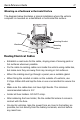
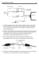
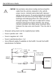
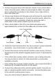
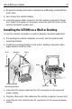
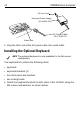
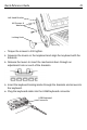
Table Of Contents
- Warranty
- Patents
- Introduction
- About This Guide
- Features
- Unpacking
- Optional Accessories
- Mounting Bracket Installation
- Installing the Desiccant Bags
- Installing the VC5090 in a Forklift
- Installing the VC5090 on a Wall or Desktop
- Installing the Optional Keyboard
- Powering the VC5090 On/Off
- Charging the Internal Backup Battery
- Calibrating the Touch Screen
- Controlling Screen Brightness
- Controlling Keyboard Backlight
- Resetting the Vehicle Computer
- Programmable Keys
- Connecting Accessories
- Maintenance
- Troubleshooting
- Regulatory Information
- Products Equipped with Bluetooth® Wireless Technology
- Country Approvals
- Health and Safety Recommendations
- FCC / EU RF Exposure Guidelines
- Power Supply
- Batteries
- Taiwan - Recycling
- Wireless Devices - Countries
- Radio Frequency Interference Requirements
- Radio Frequency Interference Requirements - Canada
- Marking and European Economic Area (EEA)
- Waste Electrical and Electronic Equipment (WEEE)

Quick Reference Guide 13
1. Connect the green wire to the vehicle's chassis. If you cannot find a
close connection point, solder an extra length of cable to the green
wire to extend the connection to the chassis. Use a heat shrink to
cover the solder joint.
2. Crimp a ring terminal onto the green wire and screw the ring terminal
into the vehicle metal work. Or, if a bolt connection exists, attach the
ring terminal to this connection (check the connection with a
multi-meter to the vehicle chassis if you’re not sure).
3. Place a fuse holder in-line of the red, black and yellow wires
approximately four inches from the cable end, as shown below.
4. Solder the fuse terminal ends to the wire to ensure a proper electrical
connection. Use a heat shrink to cover the solder joint.
VC5090
FUSE - 20A
FUSE - 1A
Ignition Switch
FUSE - 20A
Chassis ground
Vehicle
Battery
Power Cable
25-71919-01
Yellow
Red
Green
Black
Fuse Holder Fuse HolderSpring Fuse
Fuse Terminal Ends