813 VoIP Gateway User’s Guide Document Number 1813-A2-GB20-00 November 2004
1813 VoIP Gateway User’s Guide Copyright © 2004 Paradyne Corporation. All rights reserved. Printed in U.S.A. Notice This publication is protected by federal copyright law.
1813 VoIP Gateway User’s Guide Preface This manual is written to provide information to network administrators. It covers the installation, operation and applications of the 1813 VoIP Gateway. Important Safety Instructions 1. Read and follow all warning notices and instructions marked on the product or included in the manual. 2. Slots and openings in the cabinet are provided for ventilation.
1813 VoIP Gateway User’s Guide — Avoid using a telephone (other than a cordless type) during an electrical storm. There may be a remote risk of electric shock from lightning. — Do not use the telephone to report a gas leak in the vicinity of the leak. CE Marking When the product is marked with the CE mark on the equipment label, a supporting Declaration of Conformity may be downloaded from the Paradyne World Wide Web site at www.paradyne.com.
1813 VoIP Gateway User’s Guide Table of Contents CHAPTER 1 INTRODUCTION...........................................................................................................................7 1.1 PRODUCT OVERVIEW .......................................................................................................................................7 1.2 FEATURES...............................................................................................................................................
1813 VoIP Gateway User’s Guide 6
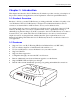
1813 VoIP Gateway User’s Guide Chapter 1 Introduction This chapter introduces the 1813 VoIP Gateway. It includes a product overview, a description of the product’s features and applications, and an explanation of the front panel LED indictors. 1.1 Product Overview Paradyne’s 1813 is a powerful VoIP Gateway, providing predictable, real-time, toll-quality voice over the Internet. The 1813 VoIP Gateway is designed for residential and business users.
1813 VoIP Gateway User’s Guide 1.
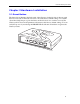
1813 VoIP Gateway User’s Guide Chapter 2 Hardware Installation 2.1 Reset Button The figure below illustrates the back panel of the Gateway. On the left side of the rear panel there is a reset button. This button is used to reload the factory default settings. Use a small object like a ballpoint pen to press the button and hold it down for over three seconds. The Gateway will be reset and all parameters will return to their factory default settings. You can verify this process by monitoring the PHONE LED.
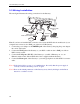
1813 VoIP Gateway User’s Guide 2.2 Wiring Installation The next figure illustrates the wiring connections for the Gateway. POWER WAN LAN 3X PHONE 2X 1X Power Cable 04-17594 Telephone Cable (RJ11) Ethernet Cable (RJ45) ADSL LAN Port ADSL Router Modem Internet Network Card Port Telephone PC Note: If you have an installed DSL connection, disconnect the RJ45 cable from the back of your computer and connect it to the WAN port of the 1813 VoIP Gateway. 1.
1813 VoIP Gateway User’s Guide 2.
1813 VoIP Gateway User’s Guide Chapter 3 Login via the Web Browser This section describes how to manage the VoIP gateway via a Web browser from the local or remote end. You can use a web browser such as Microsoft Internet Explorer version 6 or above, or Netscape Navigator version 6 or above. It is best to set your display resolution to 1024 x 768. To change the resolution, go to the Microsoft Windows control panel and click on the Display icon. You will find the display settings there.
1813 VoIP Gateway User’s Guide 3.2 Version To verify the software version of your Gateway, from the Basic Menu bar, click on Version Information. The software version is displayed.
1813 VoIP Gateway User’s Guide 3.3 Login Procedure To log on to the system from the web browser, follow the steps below: STEP 1: Start your Internet browser. STEP 2: Type the IP address for the Gateway in the Web address field. For example, if the IP address is 192.168.1.101, type http://192.168.1.101. STEP 3: You will be prompted to enter your user name and password. Type the password. The default user Name is root, and the default password is 1234. The user name and password are case-sensitive.
1813 VoIP Gateway User’s Guide Chapter 4 Basic Configuration From the Basic menu bar, you can change passwords, configure the WAN/LAN interfaces, set up routing, save settings, reboot the device, and retrieve the factory default settings. 4.1 Access Control To manage the List of Users, click on Access Control on the menu bar. On the Access Control screen, you can add or delete users, and change their passwords. 4.1.1 Change the Password To modify the password, click on Access Control on the menu bar.
1813 VoIP Gateway User’s Guide 4.1.2 Add User To add a user entry, click on the Add button, and fill out the parameters shown below. Click on Apply to submit the settings. • User Name: Enter the new user name; the User Name is case-sensitive and cannot contain spaces. • Password: Enter a password for the new user; the password is case-sensitive and cannot contain spaces. • Services: Select authorization for CLI, HTTP or FTP services. • Permissions: Select Ordinary or Administration user permission.
1813 VoIP Gateway User’s Guide 4.2 WAN Setup Click on WAN Setup from the tool bar. The following are the common settings to set up these services. Static IP address: Your Internet Service Provider (ISP) assigns you a static IP address, or the IP address of the host needs to be manually configured in your network. DHCP mode: You obtain an IP address from your ISP automatically, via DHCP protocol. PPPoE mode: Your ISP requires the use of PPPoE to connect to its service.
13 VoIP Gateway User’s Guide 4.2.1 Static IP address Select WAN Setup in the Basic Menu. Then select Static IP address (your ISP assigns you a static IP address, or an IP address of the hosts needs manually configured in your network), and click on Next. The following screen is displayed. Fill in the parameters and click on Next. WAN IP address Enter the WAN IP address. Subnet Mask The subnet mask of the selected interface.
1813 VoIP Gateway User’s Guide 4.2.2 DHCP Mode Select WAN Setup in the Basic Menu. Then select DHCP mode (the host obtains an IP address from the ISP automatically via DHCP protocol) and click on Next. The following screen is displayed. Click on Yes. 4.2.3 PPPoE PPPoE provides session authentication using either Password Authentication Protocol (PAP) or Challenge Handshake Authentication Protocol (CHAP).
1813 VoIP Gateway User’s Guide 4.3 LAN IP Address The default LAN IP address is 192.168.1.101. Click on LAN Setup from the menu bar to configure the LAN IP address and subnet mask. The following screen is displayed.
1813 VoIP Gateway User’s Guide Enter or select the parameters as explained below. Click on Apply to submit the settings. LAN IP Address Enter the LAN IP address. NetMask Enter the subnet mask of the IP network. DHCP Server Click on Enable or Disable. Starting IP Address Enter the first IP address of the address pool in the DHCP server. Note that the IP address should be in the same subnet as the Gateway’s LAN IP address.
1813 VoIP Gateway User’s Guide 4.4 Save To save the settings to Flash, click on Save & Reboot from the menu bar. In the main pane, click on Save. 4.5 Erase To erase the settings and reset to the original default click on Erase on the menu bar. In the main pane of the following display, click on Erase. Then, reboot the system.
1813 VoIP Gateway User’s Guide 4.6 Reboot To reboot the Gateway, click on Reboot from the menu bar. In the main pane, click on Reboot. Chapter 5 SIP Configuration SIP, the Session Initiation Protocol, is a signaling protocol for Internet conferencing, telephony, presence, events notification, and instant messaging. It is the Internet Engineering Task Force (IETF) standard for multimedia conferencing over IP, described in RFC 3261.
1813 VoIP Gateway User’s Guide 5.1 Introduction The SIP page appears when SIP is clicked in the in the hyperlinks menu under VoIP. This is the first and the initial screen for SIP configuration, which lists configured SIP Parameters. The screen allows the following actions to be performed. Their configurations are described in the following sections. 24 • Local: VoIP host/voice CODEC configuration for the Gateway, and SIP proxy/registrar configuration if necessary.
1813 VoIP Gateway User’s Guide 5.2 Local The Local tab configures the local terminal parameters. The page displays the SIP Configuration List. To configure the local parameters, you can click on the Config button or Modify button. The Config button changes all the local parameters based on the default settings. The Modify button configures the parameters for the selected part. The following screen appears when you select Config.
1813 VoIP Gateway User’s Guide Config Host Enter or select the SIP host parameters: Interface Choose an interface over which the SIP host will transmit /receive the SIP messages. The WAN interface is mandatory and there are no other selectable options. Transport Choose the transport protocol. It can be either UDP or TCP. The default is UDP. Presently only UDP is supported. Max Digits The limited maximum number of digits allowed. Port No Port number of user-agent where it receives the SIP messages.
1813 VoIP Gateway User’s Guide 5.3 PhoneList The PhoneList tab lists and configures the local phone parameters. This section configures the SIP parameter required to build SIP messages for the phone attached to the Gateway to send signaling information to the other party. When a call is received, the Gateway checks whether the called number matches any of the entries in the phone port list. If no entry is matched, the call request is dropped.
1813 VoIP Gateway User’s Guide DTMF The DTMF method is inband. Packetization Period The period of time that the voice packets are packetized. The value always shows 20 milliseconds. Auth User Name The authentication user name for the Registrar/proxy, which is assigned by the service provider. Auth Password The authentication password for the Registrar/proxy, which is assigned by the service provider.
1813 VoIP Gateway User’s Guide 5.4 Remote The Remote tab configures the buddy list. The Gateway looks up the buddy list for the dialed phone number first. If the phone number is not listed, then the Gateway queries the SIP proxy. It is also suitable for peer-to-peer calling in cases without a SIP Registrar/proxy. For the case without a SIP Registrar/proxy, the host phone port can’t call the user agent that is not in the buddy list.
1813 VoIP Gateway User’s Guide Add New buddy entries can be added using the Add button. After entering the parameters, click on Add to submit the settings. Modify Select the entry by ticking it in the Select field and click on Modify (see the following figure). After changing the parameters, click on Modify to submit the settings. Delete Select the entry by ticking it in the Select field and click on Delete.
1813 VoIP Gateway User’s Guide 5.5 CallForward This CallForward tab lists the configured call forward information. To configure the call forwarding parameters, tick the item and click on Modify. After changing the parameters, click on Modify to submit the settings. Phone No Displays the selected phone port number for configuration. (Port No. 1 is mandatory and is not selectable.) User Name Sip user name of the forwarding address where the calls will be forwarded.
1813 VoIP Gateway User’s Guide Chapter 6 Performance Monitoring 6.1 System Statistics To view the system statistics, click on the System Statistics button located near the bottom of the menu bar. Statistics are recorded regarding Interfaces and TCP-IP. 6.1.1 Interface Statistics To display the interface statistics, click on the Interfaces tab, located at the top-left of the System Statistics screen. The Interface Statistics page displays statistics for all interfaces.
1813 VoIP Gateway User’s Guide 6.1.2 TCP-IP To view TCP-IP statistics click on the TCP-IP tab at the top of the System Statistics page. The TCP-IP page displays the IP statistics, UDP statistics, TCP statistics, and ICMP statistics.
1813 VoIP Gateway User’s Guide 6.1.3 Ping To access the Ping screen, click on the Ping button, which is located under the Advanced menu bar. This screen performs the ping test. A ping test is used to verify the status of a network connection after the RIP or static route function is enabled. Ping sends a request message to the host and waits for a return message. This function can verify if the remote host is reachable. Ping can also measure the round-trip time to the remote host.
1813 VoIP Gateway User’s Guide The following is an example of the ping result. The information returned is as follows: Packets transmitted The number of packets that were transmitted. Packets received The number of packets that were received. Packet loss (%) The percentage of packets lost (transmitted and received) Minimum round trip time The fastest round-trip time. Maximum round trip time The slowest round-trip time.
1813 VoIP Gateway User’s Guide Chapter 7 Software Upgrade via FTP Follow the steps below to upgrade the firmware version of the Gateway via FTP. The procedures below use LAN port IP address 192.168.1.101 for illustration. STEP 1: Connect the Gateway to a PC using the LAN cable. Set the PC to the same subnet as the Gateway (192.168.1.101). STEP 2: Start an FTP program on the PC. STEP 3: Start DOS and enter the menu where the new firmware is installed: Example: C:\Upgrade STEP 4: Enter the command: ftp 192.
1813 VoIP Gateway User’s Guide STEP 10: After a moment, the file should begin transferring, after you see the message Transfer complete, the upgrade process is complete.
1813 VoIP Gateway User’s Guide Appendix A: Specifications WAN Interface Ethernet x 1 IEEE 802.3 10/100 Base-T, Auto-crossing LAN Interface Ethernet x 3 IEEE 802.
1813 VoIP Gateway User’s Guide LED WAN, LAN 1x, LAN 2x, LAN 3x, PHONE Power Supply The universal power adapter of the Gateway supports 110–240Vac. The linear power adapter of the Gateway supports 110 or 220Vac. Environmental Conditions Operating temperature 0 – 50 degrees Celsius Relative humidity 5 – 90% (non-condensing) Dimensions 150 mm (W) x 42 mm (H) x 140 mm (D) 5.9 in (W) x 1.7 in (H) x 5.
1813 VoIP Gateway User’s Guide Appendix B: Pin Assignments LAN Port (RJ45 Auto-cross) 40 Pin number Definition Pin number Definition 1 Transmit data+ 5 NC 2 Transmit data- 6 Receive data- 3 Receive data+ 7 NC 4 NC 8 NC
1813 VoIP Gateway User’s Guide Appendix C: Troubleshooting Event Checking Procedure or possible cause Unable to access the Web management Check the LAN connection. Web login reject Check your password. The default user name is root; the default password is 1234. The user name and password are case sensitive.
1813 VoIP Gateway User’s Guide Appendix D: GLOSSARY . 100BaseT: A 100 Mbps Ethernet standard that uses twisted-pair wiring. 10BaseT: A 10 Mbps Ethernet standard that uses twisted-pair wiring. address: The symbol (usually numeric) identifying an interface attached to a network. ADSL: An asynchronous form of DSL in which the bandwidth available for downstream connection is significantly larger than for upstream. analog loop: A test in which a modem’s voice signal is looped to its receiver.
1813 VoIP Gateway User’s Guide bridge: A device that links local or remote area networks together, forwarding packets based on a MAC address (compare with Gateway). broadband: Communication channels operating at transmission rates in excess of 64 kbps. broadcast: The simultaneous transmission to two or more communication devices. BT: Burst Tolerance. The limit parameter of the Generic Cell Rate Algorithm (GCRA). buffer: A temporary storage used to compensate for a difference in the rate of flow of data.
1813 VoIP Gateway User’s Guide DMT: Discrete MultiTone. The T1.413 standard modulation scheme for Digital Subscriber Line technology. DNS: Domain Name Server. A server that retains the addresses and routing information for TCP/IP PAT users. download: To receive a file over a network (compare with upload). driver: A software module that provides an interface between a network interface card and the upper-layer protocol software running on a computer. DSL: Digital Subscriber Line.
1813 VoIP Gateway User’s Guide G.991.2: An ITU-T specification for high speed DSL known as G.SHDSL. G.DMT: Another name for the G.992.1 ITU specification. G.lite: Another name for the G.992.2 ITU specification. gateway: A communications device that connects two different networks. header: The beginning of a frame or cell that contains management and addressing information. hop: One point-to-point transmission in a series required to transmit a message between two hosts in a network.
1813 VoIP Gateway User’s Guide LOC: Loss of Cell delineation. A situation where receiving equipment is unable to identify the boundaries of a cell. local analog loopback: A test in which the modem’s VF signal is looped to its receiver. local loop: An ordinary telephone line. local loopback test: An analog loopback test that loops a device’s transmitter output back to receiver input.
1813 VoIP Gateway User’s Guide node: A connection or switching point in a network, also called a host. noise: Unwanted interference to a transmitted signal by an outside source. PAP: Password Authentication Protocol. PPP protocol that ensures authentication of the connection between two devices. PAT: Port Address Translation is a form of NAT that maps multiple Private IP addresses to a single Public IP address. ping: An internet utility signal sent to check the accessibility of a device.
1813 VoIP Gateway User’s Guide remote digital loopback test: This test loops the remote digital receiver output back into the transmitter input. remote host: The computer receiving the network commands. RFC: Request for Comments. Documents published by the Internet Engineering Task Force pertaining to Internet protocols and policies. RIP: Routing Information Protocol. The protocol governing the exchange of routing information. RJ11: A 6-position jack used with dial networks and telephone sets.
1813 VoIP Gateway User’s Guide subnet: An independent network segment, that is, it has the same network address, but its subnet address is different. switch: A data switch connects computing devices to host computers, enabling multiple devices to share a limited number of ports. An electrical switch is a device for making, breaking, or changing the connections in an electrical circuit.
1813 VoIP Gateway User’s Guide VDSL: Very-high-speed DSL. A DSL protocol running at up to 52 Mbps, that is restricted to short distances. virtual circuit: A logical circuit established between two devices at the start of transmission VOD: Video On Demand. A service that provides video to subscribers upon request. VPI: Virtual Path Identifier VPI: Virtual Path Identifier. The 8-bit field in an ATM cell header that specifies the routing path for a cell. VPN: Virtual Private Network.