
User's Manual
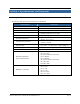
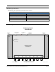
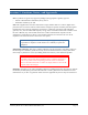
Table Of Contents

Stationary Reader User’s Manual 2001-2002 Matrics, Inc. Page 8
Section 4. Installation
Check that you have everything you need before you proceed with the installation. In addition to this
User’s Manual, you should have received the following items in your package:
• One Matrics Stationary Reader (Part# RDR-MP-001)
• Wall mount Power Supply (optional)
• Mounting equipment
• CAT5 jumper cable
• CAT3 cable termination block (“wiring block”)
• Utility software.
Contact Matrics (refer to the “Contact Us” section in this User’s Manual for more information) if any of
the above-listed items arrived damaged or are missing from your package.
LEDs and Connectors
The following table describes the Reader’s hardware. It lists the front and back panel’s connectors, etc.,
and specifies the electrical inputs and outputs:
ITEM DESCRIPTION
Power/Activity LED
LED is red when the Reader is powered On and receiving power. The
light blinks when commands are correctly received from the Host/PC.
RS485 / Bus Power
Connector
Connect to Host/PC and bus power.
RJ14 Connector For future use.
+24VDC 1.2A
Connector (Unit
Power)
The power supply should be plugged into a wall outlet and into the DC
power connector.
Mini-UHF Antenna
Connectors
Connect to external antennas.