
User's Manual

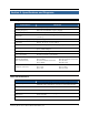
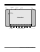
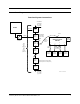
Table Of Contents
- Cover
- Notices, Trademarks, and Statement of Rights
- Contents
- Section 1. Introduction
- Section 2. System Description
- Section 3. Specifications and Diagrams
- Section 4. Getting Started
- Section 5. Installation
- Section 6. Cautions, Notes, and Approvals
- Section 7. Warranties and Returns
- Section 8. Troubleshooting
- Section 9. Contact Us

Stationary Reader User’s Manual 2001-2002 Matrics, Inc. 3
Section 3. Specifications and Diagrams
Reader Specification
CHARACTERISTIC DESCRIPTION
Name/Part Number Stationary Reader (PN: RDR-001)
Operating Frequency UHF band, 902-928 MHz, frequency hopping
System Architecture Point-to-multipoint reader network
Dimensions
12.5” wide (includes mounting plate) x 8.75” high (includes connectors)
x 1.5” deep
Simultaneous Reading Capability Up to 200 tags per second
Temperature
Operational: 0° to +50° C (+32° to +122° F)
Storage: -20° to +70° C (-4° to +158° F)
Communications Interface RS485, 232400 bps, no flow control, no parity, 8 data bits, 1 stop bit
Input/Output
4 dual coax antenna mini-UHF connectors, 1 RJ45 host comm., 1 2.5 mm
power, 1 RJ14 multiplexer
Power Supply +24 VDC, 1.2A (unregulated)
Power Consumption 30 watts operational, 1 watt standby
RJ45 Pin Assignments
(host communications)
Pin 1: Tx+ Data
Pin 2: Tx- Data
Pin 3: Power Return and Ground
Pin 4: +24VDC
Pin 5: +24VDC
Pin 6: Power Return and Ground
Pin 7: Rx- Data
Pin 8: Rx+ Data
Multiplexer connection
Pin 1: Clock+
Pin 2: Clock-
Pin 3: +12V
Pin 4: +12V
Pin 5: Tx- Data
Pin 6: Tx+ Data
LEDs and Connectors
ITEM DESCRIPTION
Power/Activity LED
LED is red when the Reader is powered on and receiving power. The
light blinks when commands are correctly received from the host PC.
RS485 / Bus Power Connector Connect to host PC and bus power.
RJ14 Connector For future use.
+24VDC 1.2A Connector
(Unit Power)
The power supply should be plugged into a wall outlet and into the DC
power connector.
Mini-UHF Antenna Connectors Connect to external antennas.