
User's Manual
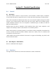
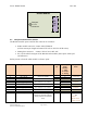
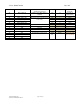
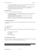
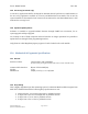
Table Of Contents
- 1.0 Revision History
- 2.0 Introduction
- 3.0 General Description
- 4.0 References
- 5.0 Product Level Specifications
- 6.0 Applicable Approvals
- 7.0 Approvals and Safety Summary
- 8.0 General
- 1.0
- 1.0
- 1.0
- 1.0
- 1.0
- 1.0
- 1.0
- 9.0 Interfaces
- 10.0 Electrical Characteristics
- 11.0 Software Features and Functions
- 12.0 Host Software
- 13.0 Mechanical & Ergonomic Specifications
- 1.0
- 14.0 Appendices

Doc #: PD001743A01 Rev. B.0
Symbol Solutions, Inc. Page 15 of 22
Symbol Confidential Restricted
Radio Module
54-
pin
I/F
Antenna
U.FL
Connector
9.1 Interface and Connection Scheme
The RA1202 module power and data bus connector is as follows:
Radio module connector: Samtec ASP-176298-02
(8.7mm custom pin lengths of Samtec FTE-125-xx-G-DV-A-P-TR series)
Mating host connector: Samtec CLE-127-01-G-DV-A-K
Pin 1 of the radio board (part of the RA1202 radio module) has a square solder pad
and silkscreen.
Below pin-out is from the radio module’s reference point.
Pin Number
Signal Name
Description
Voltage
(V)
Direction (wrt
Radio
Module)
I - Input
O - Output
A – Analog
Pull Up or Pull
Down
1
RX_I_CAL_P
Receiver differential I signal from
receiver to modem
A
Test Signal – not
connected
3
RX_I_CAL_N
A
5
GND
Ground
7
TX_Q_CAL_P
Transmitter differential Q signal
from modem to transmitter.
1V p-p
A
Test Signal –
100Kohms
9
TX_Q_CAL_N
A
11
GND
Ground
13
TX_I_CAL_P
Transmitter differential I signal
from modem to transmitter.
A
Test Signal –
100Kohms
15
TX_I_CAL_N
A
17
GND
Ground
19
ABOUT_TO_TX
Indicator when about to transmit
3.0
O
None
21
BACKUP_ACTIVE
Set when radio should go into
emergency suspend mode (ex.
Battery removal on handheld
host).
3.3
I
PD (1M on Radio
Bd)
Requires
10kohm series
resistor on host.