
User's Manual
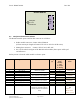
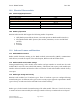
Table Of Contents
- 1.0 Revision History
- 2.0 Introduction
- 3.0 General Description
- 4.0 References
- 5.0 Product Level Specifications
- 6.0 Applicable Approvals
- 7.0 Approvals and Safety Summary
- 8.0 General
- 1.0
- 1.0
- 1.0
- 1.0
- 1.0
- 1.0
- 1.0
- 9.0 Interfaces
- 10.0 Electrical Characteristics
- 11.0 Software Features and Functions
- 12.0 Host Software
- 13.0 Mechanical & Ergonomic Specifications
- 1.0
- 14.0 Appendices

Doc #: PD001743A01 Rev. B.0
Symbol Solutions, Inc. Page 14 of 22
Symbol Confidential Restricted
Section B – Detailed Specifications
8.0 General
8.1 Description
The radio module consists of 54-pin interface, microcontroller, modem chipset, transmitter,
receiver, RF front end for transmit and receive, Tx/Rx switch and antenna port as shown below.
Host sends commands and bidirectional data to the microcontroller (MCU) through the UART
interface on the 54-pin interface. MCU sends data and control signals to the modem chipset,
which modulates the data in one of 4 of Symbol’s 4 modulation types: 2L 4800, 2L 9600, 4L
9600, 4L 19200 baud rate.
Modem outputs IQ data to transmitter, which modulates data to RF carrier, amplifies it and
outputs it on antenna port when Tx/Rx switch is set to transmit position.
When Tx/Rx switch is set into Rx positions, received data is filtered, amplified, de-modulated by
receiver and then decoded by modem. Modem sends data to MCU, where it is buffered and
relayed back to the host device.
Radio module also includes mechanical structures for support and shielding: top shield, radio
frame and bottom shield.
8.2 Block Diagram – Radio Module
Refer to confidential block diagram.
9.0 Interfaces
The figure below describes the connection and interface scheme for RA1202