RA1202 User Manual Narrow Band UHF Radio Symbol Technologies Inc. RA1202 User Manual DOC. NO: PD001743A01 SHEET 1 OF 44 REVISION : B.
Doc #: PD001743A01 Rev. B.0 Table of Contents 1.0 Revision History .................................................................................................................. 5 2.0 Introduction .......................................................................................................................... 6 3.0 General Description ............................................................................................................. 6 4.0 References ..........................
Doc #: PD001743A01 Rev. B.0 Colocated Transmitters .................................................................................................. 13 7.8 8.0 General ............................................................................................................................... 14 8.1 Description ..................................................................................................................... 14 8.2 Block Diagram – Radio Module ..................................
Doc #: PD001743A01 Rev. B.0 Labeling Requirements ............................................................................................... 21 13.4 14.0 Appendices ......................................................................................................................... 22 14.1 General........................................................................................................................ 22 14.2 Receiver ...........................................................
Doc #: PD001743A01 Rev. B.0 1.0 Revision History REV DESCRIPTION DATE Author A.0 Initial Release Sep. 12, 2014 Armia Nazeer B.0 - Added regulatory comments as per Ultratech’s request. Sep. 18, 2014 Sada, Irfan, Armia - Removed confidential information. Ex. Block diagram Symbol Solutions, Inc.
Doc #: PD001743A01 2.0 Rev. B.0 Introduction This document is the user manual for the RA1202 Narrow Band Radio module. It describes its function and specifications as well as general architectural details. All references to Symbol in this document refer to Symbol Technologies Inc. 3.0 General Description RA1202 is a Narrow Band UHF radio module for data only (no audio) communications.
Doc #: PD001743A01 4.0 4.1 Rev. B.0 References Applicable Documents and Drawings – Symbol Technologies Doc./Dwg No.
Doc #: PD001743A01 5.0 Rev. B.0 Product Level Specifications The RA1202 provides narrowband data communications using legacy Symbol proprietary narrowband protocol and FM modulation schemes. These include: 2 level FSK running at 4800 and 9600 bps 4 level FSK running at 9600 and 19,200 bps The RA1202 is functionally backward compatible for all modulations with currently existing Symbol narrowband radios including RA1001A; RA1001; TRX7370, TRX7355 (4 level modulations only).
Doc #: PD001743A01 5.4 Rev. B.0 Polling protocol and cellular protocol is supported. New polling protocol and non-Cellular is not supported. TESS and ANSI DATA stream as payload is supported via Open TekTerm application for terminals. Support and Test Software The following software is available for use with the RA102 radio module: RTest command line utility which can used by manufacturing to configure the radio parameters or alternatively to operate radio test only modes.
Doc #: PD001743A01 5.7 RF Connectivity 5.8 Rev. B.0 Frequency range: - 403 - 435 MHz, 435 – 470 MHz Data rate & modeError! Bookmark not defined.: 2 level FSK 4800 bps, 1 2 level FSK 9600 bps 4 level FSK 9600 bps 4 level FSK 19.2 Kbps RF Power: Factory set to 0.45 watt (non-US) or 1 watt Channel Spacing: 12.5 KHz 20 KHz (non-US & Canada) 25 KHz (not for Part 90) Sensitivity2: 0.5uV nominal @ 1% BER [12.5 kHz] or better 0.
Doc #: PD001743A01 iii. iv. v. Rev. B.0 a. Modular compliance and approval as per RSS-119 section (IEC-003) unintentional emissions. ETSI EN 300-113 Compliance ETSI EN 300-220 Compliance FCC, IC, ETSI – coexistence of Radio Approvals a. When RA1202 radio module is integrated into XT15 and VH10 host devices, coexistence of NB Radio with WLAN and BT as applicable by: i. FCC CFR47 Part 90 (Tx harmonics) and Part 15 subpart B class B ii. Industry Canada RSS-190 (IEC003) Tx harmonics iii.
Doc #: PD001743A01 7.1 Rev. B.0 FCC Information to Users For Class B Unintentional Radiators: This equipment has been tested and found to comply with the limits for a Class B digital device, pursuant to Part 15 of the FCC Rules. These limits are designed to provide reasonable protection against harmful interference in a residential installation.
Doc #: PD001743A01 Rev. B.0 IC: 1549L-RA1202” 7.5 Labeling Requirement for Host After installing the radio module in a host if the label is not visible from outside then a separate label has to be affixed to the outside of the host with following information: “Contains Symbol Technologies Inc UHF Radio, Model RA1202 FCC ID: H9PRA1202 IC: 1549L-RA1202” 7.
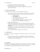
Doc #: PD001743A01 Rev. B.0 Section B – Detailed Specifications 8.0 General 8.1 Description The radio module consists of 54-pin interface, microcontroller, modem chipset, transmitter, receiver, RF front end for transmit and receive, Tx/Rx switch and antenna port as shown below. Host sends commands and bidirectional data to the microcontroller (MCU) through the UART interface on the 54-pin interface.
Doc #: PD001743A01 Rev. B.0 Radio Module 54pin I/F Antenna U.FL Connector 9.1 Interface and Connection Scheme The RA1202 module power and data bus connector is as follows: Radio module connector: Samtec ASP-176298-02 (8.7mm custom pin lengths of Samtec FTE-125-xx-G-DV-A-P-TR series) Mating host connector: Samtec CLE-127-01-G-DV-A-K Pin 1 of the radio board (part of the RA1202 radio module) has a square solder pad and silkscreen. Below pin-out is from the radio module’s reference point.
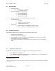
Doc #: PD001743A01 23 WAN_PWR_EN 25 MCU_PWR_EN 27 29 31 33 35 37 39 41 43 45 47 49 51 53 GND MCU_UART2_RX MCU_UART2_CTS MCU_UART2_TX MCU_UART2_RTS JTAG_TRST_N/SPARE-2 GND GND GND GND VSYS VSYS VSYS VSYS Symbol Solutions, Inc. Symbol Confidential Restricted Rev. B.0 Power enable for the radio module from the hsot Indicator when MCU power is enabled Ground MCU serial port 2 (RS232 channel to the host) Ground Ground Ground Ground Radio Module Power Supply Page 16 of 22 3.
Doc #: PD001743A01 Rev. B.0 Pin Number Signal Name Description 2 4 6 8 RX_Q_CAL_N RX_Q_CAL_P GND UPS_MODE Receiver differential Q signal from receiver to modem Ground Indicator from Host to MCU radio to go into lower power mode.
Doc #: PD001743A01 Rev. B.0 10.0 Electrical Characteristics 10.1 Power Supply Requirements Input Voltage Range Nominal Input Voltage Current consumption at nominal input voltage OFF Idle Receive Transmit 3.2 to 4.2 Vdc 3.7Vdc TBD mA TBD mA <200mA 1.5A nominal at 1Watt output 10.
Doc #: PD001743A01 Rev. B.0 Locked and signed software does not allow access to commands to modify radio type. Control panel in windows can only read the radio type. Password protection. This is added security beyond the locked and signed software. Specialized commands to change radio types, which are only available in manufacturing and authorized service depots. 11.
Doc #: PD001743A01 Rev. B.0 12.3 Site Survey (terminals only) A site survey application shall be developed for RA1202 that will perform in a similar manner to the site survey application available on 7530 G2 and 8525/8530 G2 terminals. This is used by system installers to determine the best location of base stations for new NarrowBand sites. It also indicates the coverage level. 12.
Doc #: PD001743A01 Rev. B.0 13.3 Environmental Conditions Storage temperature: Operating temperature: Humidity*: -35C to +85C -30C to +80C 5% to 95% (non-condensing) Temperature shock*: -30C to +50C (85% R.H.) as per MIL-STD810G; Method 503.5 Procedure I-C (Multicycle shocks) * There will be NO environmental protection on the RA1202 radio module, as it is designed to be fully enclosed within a host unit. 13.
Doc #: PD001743A01 Rev. B.0 14.0 Appendices Radio Performance Specifications 14.1 General Frequency Range: Frequency Control: Channel Spacing: Mode of Operation: Regulated Supply Voltage: Operating Temperature Range: Maximum Dimensions: Weight: FCC Compliance: 435-470 MHz [high band – FCC, IC, EU, & other] 403-435 MHz [low band – non-FCC, non-IC] Synthesized 12.5 kHz [FCC & others] 20 kHz [non-FCC] 25 kHz non Part 90 Simplex or Half Duplex 3.7VDC +/- 15% -30C to +80C 64 (W) x 52.5 (L) x 17.1 (H) mm 37.