P L 4 C 7 r 0 a B d l a s e e Preliminary
P L 4 7 0 B a s e C r a d l e 1998 SYMBOL TECHNOLOGIES, INC. All rights reserved. Symbol reserves the right to make changes to any product to improve reliability, function, or design. Symbol does not assume any product liability arising out of, or in connection with, the application or use of any product, circuit, or application described herein.
Q u i c k R e f e r e n c e Introduction The PhaserLink PL 470 Base Cradle acts as a stand, host communication interface, and a charger for the Phaser Radio Scanner. It can sit on a desktop or be wall-mounted - whichever is more convenient. The cradle receives data from the scanner via connectors in the bottom of the scanner and the top of the cradle. It then transmits that data to the host device through an attached cable.
P L 4 7 0 B a s e C r a d l e P 370/470 Radio Scanner Quick Reference Guide, p/n 72-xxxxx-xx Preliminary 2
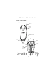
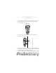
Q u i c k R e f e r e n c e Parts of the Cradle This figure shows the parts of the PhaserLink Cradle: Antenna Scanner Support Tab Charging/ Communications Contacts Charging LED Indicator COM 1 Power Port COM 2 Wallmounting Socket 1 Wallmounting Socket 2 Preliminary 3
P L 4 7 0 B a s e C r a d l e Connecting To The Host On the bottom of the cradle are three ports - COM 1 COM 2 Power Port COM 1 connects to the host computer, COM 2 is used for daisychaining multiple cradles together, and the Power Port supplies power to the cradle. 1. Insert the independent power plug into the Power Port (the cradle cannot be powered by the host computer).
Q u i c k R e f e r e n c e 2. Insert the cable from the host computer into COM 1 and the cable to the other cradles, if any, into COM 2. Daisy-Chaining Note: The cradle supports daisy-chaining when connected to a serial host and not when using Synapse interfaces. To daisy-chain two or more cradles together, connect COM 1 of the first cradle to the host and COM 2 to COM 1 of the second cradle. Then connect COM 2 of the second cradle to COM 1 of the third cradle.
P L 4 7 0 B a s e C r a d l e 2. Seat the cables from the bottom of the cradle in the grooves along the length of it so that the bottom of the cradle is smooth and flat, as shown: 3. Secure two screws (included) to the wall. A template is provided for you on page 12. 4. Fasten the screws into the wall where the cradle will hang, leaving about 1/8” (.3 cm) of the screw outside the wall so that the cradle will have something to hang on. 5.
Q u i c k R e f e r e n c e Inserting Phaser in the Cradle Place the Phaser scanner in the cradle so that the top of the scanner sits in the larger part of the cradle and the metal contacts on the bottom of the scanner touch the contacts on the cradle, like so: Sending Data to Host Computer To set up the PhaserLink Cradle for communications between a Phaser and a host computer: 1. Connect the cradle to the host computer as described in Connecting To The Host on page 4. 2. Insert the Phaser in the cradle.
P L 4 7 0 B a s e C r a d l e Indicator LED Once the scanner is placed in the cradle, it will wait 15 minutes to start charging the battery in the scanner.
Q u i c k R e f e r e n c e Regulatory Information Cradle Labeling Radio Frequency Interference Requirements This device has been tested and found to comply with the limits for a Class A digital device pursuant to Part 15 of the Federal Communications Commissions Rules and Regulation. These limits are designed to provide reasonable protection against harmful interference when the equipment is operated in a commercial environment.
P L 4 7 0 B a s e C r a d l e • Connect the equipment into an outlet on a circuit different from that which the receiver is connected. • Consult the dealer or an experienced radio/TV technician for help. Radio Frequency Interference Requirements - Canada This Class A digital apparatus meets the requirements of the Canadian InterferenceCausing Equipment Regulations. Cet appareil numérique de la Classe A respecte toutes les exigences du Reglement sur le Materiél Brouilleur du Canada.
Q u i c k R e f e r e n c e Service Information Before you use the cradle , it must be configured to operate in your facility’s network and run your applications.If you have a problem with running your cradle or using your equipment, contact your facility’s Technical or Systems Support. If there is a problem with the equipment, they will contact the Symbol Support Center: 1-800-653-5350 Outside North America, contact your local Symbol representative.
P L 4 7 0 B a s e C r a d l e Wall Mounting Template: 1 5/16” Wall Mounting Socket 1 Use 1/8” drill bit for the screw holes.
Q u i c k R e f e r e n c e this page intentionally left blank Preliminary 13
Preliminary 70-38494-01 Revision .1 — June 1999 Symbol Technologies, Inc.