D T 7 5 0 0 S e r i e s PR EL IM IN A R Y P
P D T 7 5 0 0 S e r i e s IN A R Y 1999-2000 SYMBOL TECHNOLOGIES, INC. All rights reserved. Symbol reserves the right to make changes to any product to improve reliability, function, or design. Symbol does not assume any product liability arising out of, or in connection with, the application or use of any product, circuit, or application described herein.
Q u i c k R e f e r e n c e Introduction R Y The PDT 7500 Series family of portable data terminals puts the processing power of a 486 PC in the user’s hand. The terminal uses a rechargeable Lithium-Ion 1400 mAh smart battery, and incorporates pen technology and bar code scanning capability in a key-based terminal. The PDT 7500 ruggedized hand-held terminal combines: A PR EL • • • • IN • PC-standard architecture (32-bit 486 DX2) Microsoft® MS-DOS 6.
P D T 7 5 0 0 S e r i e s About This Guide A R Parts of the PDT 7500 on page 3 Installing New or Recharged Batteries on page 5 Operating the PDT 7500 on page 8 Using the PDT 7500 Keypad on page 11 Using the Integrated Laser Scanner on page 12 Host Communications on page 15 Using the Touch Screen on page 16 Troubleshooting on page 16. IN • • • • • • • • Y This guide provides information on the operation of the PDT 7500 Series terminal.
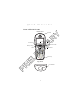
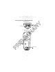
Q u i c k R e f e r e n c e Parts of the PDT 7500 Scan LED R Y Front View A LCD Scan Button Thumb Rest Power Key Top View PR EL IM IN Communication LED Battery Charge LED Scan Window 3
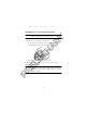
P D T 7 5 0 0 S e r i e s Parts of the PDT 7500 (continued) Y Bottom View Serial Communications Port EL IM IN Back View A R IrDA Port PR Li-Ion Battery Battery Latch 4
Q u i c k R e f e r e n c e Installing New or Recharged Batteries To ensure proper terminal operation, use ONLY the Symbol Li-Ion battery in the PDT 7500. To install a new or recharged Li-Ion battery: R Y Caution: IM IN A 1. Hook the base of the new battery in the top of the battery compartment, then press the into place. EL 2. Slide the battery latch to secure the battery. If the battery latch is not closed, do not operate the terminal, otherwise data may be lost.
P D T 7 5 0 0 S e r i e s Removing the Battery from the Terminal To remove the Li-Ion battery from the terminal: Y 1. Suspend the terminal’s power. IM IN A R 2. Slide the battery release switch towards the top of the terminal until the lock releases. PR EL 3. Lift the battery up and out of the battery compartment. Charging the Battery in the Terminal To charge the terminal’s battery, place the PDT 7500 in the cradle or connect the synchronization/charging cable.
Q u i c k R e f e r e n c e Y For instructions on setting up the cradle, refer to the Quick Reference Guide that shipped with your cradle or to the PDT 7500 Series Product Reference Guide (72-39225-xx for DOS terminals, or 72-41235-xx for Windows CE Terminals). Charging the Spare Battery IN A R The cradle also has a spare battery charging slot. To charge the spare Li-Ion battery in the CRD 7500 cradle, place the battery into the charging slot in the cradle.
P D T 7 5 0 0 S e r i e s Operating the PDT 7500 Powering the Terminal On/Off Y Before the terminal can be powered on, it must be initialized and the battery must be fully charged. Refer to the PDT 7500 Series Product Reference Guide for your terminal for information on initializing the terminal. R Note: A To power on the terminal: 1. Make sure the terminal’s battery is fully charged. IN 2. Press the PWR key. To suspend the terminal’s operation, press the PWR key.
Q u i c k R e f e r e n c e Performing a Cold Boot (DOS and Windows CE Terminals) Y A cold boot restarts the terminal. In the Windows CE environment, the registry and objects stored are reset to original settings. R To perform a cold boot, press and hold the PWR key for 15 seconds, then release. On the DOS terminal, this value can be reconfigured in Setup (see the Product Reference Guide for more information).
P D T 7 5 0 0 S e r i e s To calibrate your PDT 7500 terminal: Y 1. If necessary, adjust the contrast on the PDT 7500 so the screen is clear and readable. See “Controlling the Screen Contrast” on page 8 for instructions. IM IN A R 2. As the screen instructs, carefully press and briefly hold the stylus on the center of each target. Repeat as the target moves around the screen. PR EL 3. Tap the screen when prompted to accept new calibration.
Q u i c k R e f e r e n c e Using the PDT 7500 Keypad R Y The PDT 7500 uses an alphanumeric keypad that produces the 26character alphabet (A-Z), numbers (0-9), and assorted characters. The keypad is color-coded to indicate which modifier key (ALPHA, CTRL, FUNC, and SHIFT) to press to produce a particular character or action. A Alpha key Function key Control key IM Enter key IN Shift key EL Power key • • • • • • Backspace key Space key The default numeric keypad produces the numbers 0-9.
P D T 7 5 0 0 S e r i e s Press ENTER after entering data or a command. Press CTRL to perform the control function. This key is under application control. • Press SHIFT and a key to produce various character keys; refer to the PDT 7500 Series Product Reference Guide for your terminal or your application guide for the keypad mapping. Note: Key function can be changed by an application. Your keypad may not function exactly as described above.
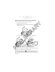
Q u i c k R e f e r e n c e Scanning PDF417 Bar Codes Y The PDF417 bar code symbol has multiple rows, but the raster pattern also has multiple scanning rows. Two basic steps are required as you scan: IN Slab Raster A R 1. Point the scanner at the bar code and press the scan button. EL IM 2. As the raster pattern spreads, keep the pattern in the same horizontal plane as the bar code. 3/4” 3/4” PR 3.
7 5 0 0 S e r i e s IN A R Y P D T PR EL IM The scan beam does not have to be perfectly parallel with the top and bottom of the symbol (up to a 4o tilt will work).
Q u i c k R e f e r e n c e Host Communications A Using the RS-232 Serial Cable R Y The PDT 7500 Series terminal can communicate with a host PC either directly through its communications port using an RS-232 serial cable or the cradle, or wirelessly via the Spectrum24® wireless LANs. For more information on setting up and performing wireless communications with your PDT 7540 terminal, refer to the PDT 7500 Series Product Reference Guide.
P D T 7 5 0 0 S e r i e s Communicating with Printers Using the Touch Screen A R Y The PDT 7500 communicates with IrDA-compliant peripherals through the IrDA interface in the base of the terminal. To print, point the PDT 7500’s IrDA port at the IrDA port on the IrDAcompliant printer from a maximum distance of 39 inches (1 meter) and run the application’s print function. Printer communication can also be established through an RS-232 cable connected directly to the printer.
Q u i c k Problem Cause Solution Press the PWR key. Contrast not adjusted properly. Press the blue FUNC key and then the Dark or Light keys to adjust contrast. Scanner does not power on when the scan button is pressed. Scanner is not enabled. See your System Administrator. Scanner does not decode a bar code. Bar code is unreadable. Verify that the bar code is not defective, i.e., smudged or broken. Scan window is dirty. Clean scan window with a lens tissue. Tissues for eyeglasses work well.
P D T Cause Solution Bring the terminal closer to the printer and attempt communications again. Obstruction interfered with communication. Check the path to ensure no objects were in the way. Application is not enabled to run IrDA printing. Printer support must be included with the application to run IrDA printing on the terminal. See your System Administrator. R Y Distance from printer is more than 1 meter (3.28 feet). PR EL IM IN Fail to communicate with IrDA printer.
Q u i c k R e f e r e n c e GND 2 DSR 3 RXD 4 CTS 5 DCD 6 GND IN 1 R Description A Pin Y Pin-Outs 7 PWROUT (+5V) 8 PWRIN(+15V) 10 11 EL 12 DTR IM 9 Ring TXD RTS Reserved 14 GND 15 PWRIN(+15V) PR 13 Regulatory Information Radio Frequency Interference Requirements This device has been tested and found to comply with the limits for a Class A digital device pursuant to Part 15 of the Federal Communications Commissions Rules and Regulation.
P D T 7 5 0 0 S e r i e s R Y However, there is no guarantee that interference will not occur in a particular installation. If the equipment does cause harmful interference to radio or television reception, which can be determined by turning the equipment off and on, the user is encouraged to try to correct the interference by one or more of the following measures: • Re-orient or relocate the receiving antenna. • Increase the separation between the equipment and receiver.
Q u i c k R e f e r e n c e Applicable Standards Laser Devices IN A R Y • EN 55 022 - Limits and Methods of Measurement of Radio Interference Characteristics of Information technology Equipment • EN 55024:1998; Information technology equipment-Immunity characteristicsLimits and methods of measurement.
P D T 7 5 0 0 S e r i e s A R Y Scanner Labeling IN AVOID EXPOSURE - LASER LIGHT IS EMITTED FROM THIS APERTURE EL IM ÉVITER TOUTE EXPOSITION LUMIÈRE LASER ÉMIS PAR CETTE OUVERTURE PR This label is located inside the battery compartment.
Q u i c k R e f e r e n c e DUTCH KLASSE 1 KLASSE 2 ITALIAN CLASSE 1 CLASSE 2 KLASSE-1 LASERPRODUKT LASERLICHT NIET IN STRAAL STAREN KLASSE-2 LASERPRODUKT LUOKKA 1 LASERTUOTE LASERVALO ÄLÄ TUIJOTA SÄDETTÄ LUOKKA 2 LASERTUOTE EL FINNISH LUOKKA 1 LUOKKA 2 KLASSE 1 LASERPRODUKT LASERLYF SE IKKE IND I STRÅLEN KLASSE 2 LASERPRODUKT AL LASER DI CLASSE 2 IN DANISH KLASSE 1 KLASSE 2 HEBREW CLASS 1 LASER PRODUCT LASER LIGHT DO NOT STARE INTO BEAM CLASS 2 LASER PRODUCT IM ENGLISH CLASS 1 CLASS 2 A R Y
P D T 7 5 0 0 S e r i e s Service Information 1-800-653-5350 Canada 905-629-7226 United Kingdom 0800 328 2424 Asia/Pacific 337-6588 Australia 1-800-672-906 Austria 1-505-5794 Denmark 7020-1718 Finland 01-40-96-52-21 Germany Italy 2-484441 Mexico Netherlands 315-271700 South Africa 11-4405668 Sweden 84452900 6074-49020 5-520-1835 Norway 66810600 Spain 9-1-320-39-09 1-800-347-0178 Inside US +1-561-483-1275 Outside US IM Latin America Sales Support 9 5407 580 IN France
Q u i c k R e f e r e n c e Warranty Coverage and Procedure EL General IM IN A R Y During the warranty period, Symbol will repair or replace defective products returned to Symbol’s manufacturing plant in the US. For warranty service in North America, call the Symbol Support Center at 1-800-653-5350. International customers should contact the local Symbol office or support center. If warranty service is required, Symbol will issue a Return Material Authorization Number.
Y R A IN IM EL PR 72-38888-02 Revision A — April 2000 Symbol Technologies, Inc.