
Reference Guide
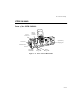
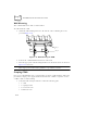
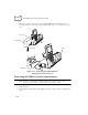
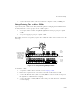
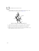
Table Of Contents
- About This Guide
- Chapter 1 Getting Started
- Chapter 2 Accessories Setup
- Chapter 3 Batch and Spectrum One Terminal Setup
- Chapter 4 Spectrum24 RF Terminal Setup
- Chapter 5 Operating the PDT 6800 Series
- Chapter 6 Maintaining the Terminal
- Chapter 7 Error Recovery and Troubleshooting
- Appendix A Null Modem Pin-outs
- Appendix B Keyboard Layouts
- Appendix C Communications Status Codes
- Appendix D Specifications
- Appendix E Boot-Up Quick Reference
- Appendix F 2D Scanner Drivers and Applications
- Numerics
- A
- B
- C
- D
- E
- F
- I
- K
- L
- M
- N
- P
- R
- S
- T
- U
- W

2-18
PDT 6800 Series Product Reference Guide
3. Attach the PIM’s optical connector to the terminal by inserting the clips on the
connector in the slots on either side of the port (Figure 2-18).
Figure 2-18. Attaching the PIM’s Optical Connector
1. Connect the RS-232 cable’s DB-25 connector in the PC Adapter’s RS-232 port.
2. Plug the other end of the RS-232 cable in the RS-232 device (e.g., host PC).
3. Plug the jack end of the 16-Volt power supply into the power supply port.
4. Plug the 15-Volt power supply’s cube into an electrical outlet. The Battery Charge
Indicator LED flashes when the terminal is powered on.
Clips
Slots
Optical
Port
PIM Cable
PIM Optical
Connector