
Reference Guide
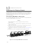
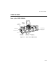
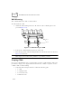
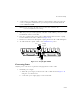
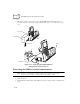
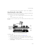
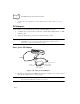
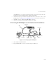
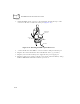
Table Of Contents
- About This Guide
- Chapter 1 Getting Started
- Chapter 2 Accessories Setup
- Chapter 3 Batch and Spectrum One Terminal Setup
- Chapter 4 Spectrum24 RF Terminal Setup
- Chapter 5 Operating the PDT 6800 Series
- Chapter 6 Maintaining the Terminal
- Chapter 7 Error Recovery and Troubleshooting
- Appendix A Null Modem Pin-outs
- Appendix B Keyboard Layouts
- Appendix C Communications Status Codes
- Appendix D Specifications
- Appendix E Boot-Up Quick Reference
- Appendix F 2D Scanner Drivers and Applications
- Numerics
- A
- B
- C
- D
- E
- F
- I
- K
- L
- M
- N
- P
- R
- S
- T
- U
- W

2-17
Accessories Setup
The LED flashes once when the terminal is turned on. It remains steady while the
terminal is powered and blinks slowly during downloading.
!
The RS-232 25-pin port attaches the null modem cable connected to a PC or other
RS-232 device. See Appendix A, Null Modem Pin-outs for null modem pin-outs.
!
The DB-9 connector attaches the PIM’s DB-9 connector.
!
The power supply port attaches the 15-Volt power supply.
Connecting the PC Adapter to the Terminal and Serial Device
Figure 2-17. Setting Up the PC Adapter
1. Turn the PC and terminal OFF.
2. Plug the PIM’s DB-9 connector in the PC Adapter’s DB-9 port.
PIM
DB-9 Port
PIM’s Optical
Connector
PC
Adapter
DB-25RS-232 Cable
Connector
Power Supply
Power
Supply
Port