
Reference Guide
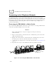
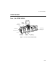
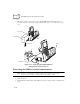
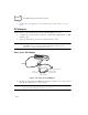
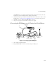
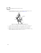
Table Of Contents
- About This Guide
- Chapter 1 Getting Started
- Chapter 2 Accessories Setup
- Chapter 3 Batch and Spectrum One Terminal Setup
- Chapter 4 Spectrum24 RF Terminal Setup
- Chapter 5 Operating the PDT 6800 Series
- Chapter 6 Maintaining the Terminal
- Chapter 7 Error Recovery and Troubleshooting
- Appendix A Null Modem Pin-outs
- Appendix B Keyboard Layouts
- Appendix C Communications Status Codes
- Appendix D Specifications
- Appendix E Boot-Up Quick Reference
- Appendix F 2D Scanner Drivers and Applications
- Numerics
- A
- B
- C
- D
- E
- F
- I
- K
- L
- M
- N
- P
- R
- S
- T
- U
- W

2-16
PDT 6800 Series Product Reference Guide
5. Connect the power supplies for each coupled section as directed in Connecting
Power.
PC Adapter
The PC Adapter works with the Printer Interface Module (PIM) so you can:
!
Communicate to and from the PC without a CCM 38/6860, CRD 38/6865, or CRD
38/6866 cradle
!
Charge the NiCd battery pack in the terminal without a cradle.
Note: The Lithium Ion battery DOES NOT charge when the PC Adapter
and PIM are connected. Use the UBC 2000 battery adapter p/n 21-
32665-24 to charge the Lithium Ion battery.
Parts of the PC Adapter
Figure 2-16. Parts of the PC Adapter
!
The Battery Charge Indicator LED flashes when the terminal power is turned on and
while the NiCd battery pack is being charged.
Note: When power to the PC Adapter is turned on, NiCd battery charging
begins automatically and continues for 7 hours.
PIM
RS-232
Pin Port
DB-9 Connector
Battery Charge
Indicator LED
Power Supply Port
PC Adapter