
Reference Guide
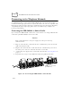
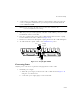
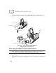
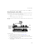
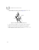
Table Of Contents
- About This Guide
- Chapter 1 Getting Started
- Chapter 2 Accessories Setup
- Chapter 3 Batch and Spectrum One Terminal Setup
- Chapter 4 Spectrum24 RF Terminal Setup
- Chapter 5 Operating the PDT 6800 Series
- Chapter 6 Maintaining the Terminal
- Chapter 7 Error Recovery and Troubleshooting
- Appendix A Null Modem Pin-outs
- Appendix B Keyboard Layouts
- Appendix C Communications Status Codes
- Appendix D Specifications
- Appendix E Boot-Up Quick Reference
- Appendix F 2D Scanner Drivers and Applications
- Numerics
- A
- B
- C
- D
- E
- F
- I
- K
- L
- M
- N
- P
- R
- S
- T
- U
- W

2-15
Accessories Setup
3. Connect the cable’s other connector to the host computer’s serial (COMM) port.
Daisy-Chaining Two or More CCMs
Up to twenty-four CCMs can be daisy-chained together for charging and communications.
To daisy chain two or more groups of four CCMs requires:
!
one 25-pin, male-to-female, straight-through RS-232 cable per group of coupled
CCMs
!
one power supply per group of coupled CCMs.
Depending on how close together you place the CCMs, the cables can be from 1-foot to 10-
feet long.
Figure 2-15. Daisy-Chaining Multiple CCMs
To chain the CCMs:
1. Couple the CCMs as directed in the section Coupling CCMs.
2. In the first coupled section, connect the serial cable to the left-most CCM.
3. Connect the RS-232 cable’s (male or female) DB-25 connector in the serial port of
the right-most CCM in the first coupling.
4. Connect the (male or female) DB-25 in the serial port of the left-most CCM in the
second coupling.
One Power Supply
and RS-232 Cable
per Group of
Coupled CCMs
First
Coupled
Group
Second
Coupled
Group
RS-232
Cable
(a “Group” Can
Number from
1 to 4 CCMs)