
Reference Guide
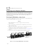
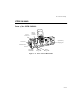
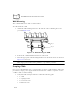
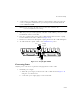
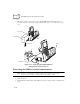
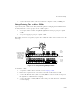
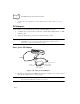
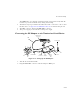
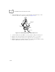
Table Of Contents
- About This Guide
- Chapter 1 Getting Started
- Chapter 2 Accessories Setup
- Chapter 3 Batch and Spectrum One Terminal Setup
- Chapter 4 Spectrum24 RF Terminal Setup
- Chapter 5 Operating the PDT 6800 Series
- Chapter 6 Maintaining the Terminal
- Chapter 7 Error Recovery and Troubleshooting
- Appendix A Null Modem Pin-outs
- Appendix B Keyboard Layouts
- Appendix C Communications Status Codes
- Appendix D Specifications
- Appendix E Boot-Up Quick Reference
- Appendix F 2D Scanner Drivers and Applications
- Numerics
- A
- B
- C
- D
- E
- F
- I
- K
- L
- M
- N
- P
- R
- S
- T
- U
- W

2-14
PDT 6800 Series Product Reference Guide
2. When the CCM is connected to power, all the LEDs flash at the same time for 3
seconds, flash once from left to right, and then turn on for 3 seconds before going
out.
Figure 2-14. Connecting the CCM 38/6860 for
Charging and Communications
Connecting the CCM for Serial Communications
Note: Both the communications cables and the power supply connection are
required for performing communications through the CCM.
1. Turn off the PC.
2. Plug the RS-232 null modem cable’s DB-25 connector in the cradle’s communication
port.
+-
+
-
Power Supply
Insert Screw
Insert Screw
LEDs
CCM
Null Modem Cable