
Reference Guide
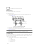
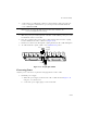
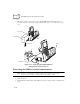
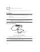
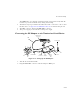
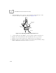
Table Of Contents
- About This Guide
- Chapter 1 Getting Started
- Chapter 2 Accessories Setup
- Chapter 3 Batch and Spectrum One Terminal Setup
- Chapter 4 Spectrum24 RF Terminal Setup
- Chapter 5 Operating the PDT 6800 Series
- Chapter 6 Maintaining the Terminal
- Chapter 7 Error Recovery and Troubleshooting
- Appendix A Null Modem Pin-outs
- Appendix B Keyboard Layouts
- Appendix C Communications Status Codes
- Appendix D Specifications
- Appendix E Boot-Up Quick Reference
- Appendix F 2D Scanner Drivers and Applications
- Numerics
- A
- B
- C
- D
- E
- F
- I
- K
- L
- M
- N
- P
- R
- S
- T
- U
- W

2-13
Accessories Setup
2. On the add-on (or right-hand) CCM, use a 3/16-inch driver and remove the jack
screws, securing the communications port, and replace them with the flat-head
screws ONE AT A TIME.
Note: Be sure to remove the jack screws one at a time; otherwise, the
connector will fall into the housing.
3. Mate the power port on the right side of the first cradle with the power port on the
left hand side of the second cradle.
4. Place the coupling bracket between the CCMs, aligning the holes in the coupling
bracket with the holes in the CCM’s base (Figure 2-13).
5. Install 6 cross-head screws through the coupling bracket into the CCMs and tighten.
6. To wall mount the coupled CCMs, refer to Wall Mounting above.
Figure 2-13. Coupling Two CCMs
Connecting Power
Only the power connection is required for charging batteries in the CCM.
1. Install the power supply.
a. Attach the power supply to the left side of the CCM as shown in Figure 2-14
using two cross-head screws.
b. Connect the power supply plug to an AC wall outlet.
Screws
Coupling
Bracket
Screws