
Reference Guide
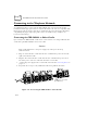
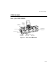
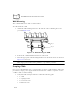
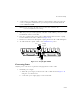
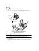
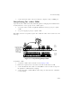
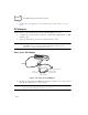
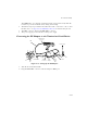
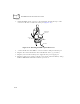
Table Of Contents
- About This Guide
- Chapter 1 Getting Started
- Chapter 2 Accessories Setup
- Chapter 3 Batch and Spectrum One Terminal Setup
- Chapter 4 Spectrum24 RF Terminal Setup
- Chapter 5 Operating the PDT 6800 Series
- Chapter 6 Maintaining the Terminal
- Chapter 7 Error Recovery and Troubleshooting
- Appendix A Null Modem Pin-outs
- Appendix B Keyboard Layouts
- Appendix C Communications Status Codes
- Appendix D Specifications
- Appendix E Boot-Up Quick Reference
- Appendix F 2D Scanner Drivers and Applications
- Numerics
- A
- B
- C
- D
- E
- F
- I
- K
- L
- M
- N
- P
- R
- S
- T
- U
- W

2-12
PDT 6800 Series Product Reference Guide
Wall Mounting
The CCM 38/6860 can be table or wall mounted.
To wall mount the CCM:
1. Attach the wall-mounting brackets to the bottom of the CCM using the screws
provided (Figure 2-12)
Figure 2-12. Wall Mounting the CCM
2. Position the CCM with attached brackets on the wall.
3. Insert the appropriate wall-mounting hardware into the bracket holes as shown in
Figure 2-12 and secure.
Note:
Appropriate wall-mounting hardware is provided by customer.
Coupling CCMs
Up to four CCM 38/6860s can be coupled together for table or wall mounting, with power
provided by a single power supply attached to the left-most CCM. To couple two or more
CCMs for table or wall mounting:
1. Verify that add-on kit p/n 3861-101 contains the following parts:
" 1 CCM
" 1 coupling bracket
" 6 cross-head screws
" 2 flat-head screws
Step 1
Step 2