
Reference Guide
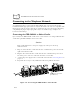
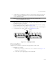
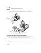
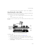
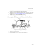
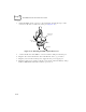
Table Of Contents
- About This Guide
- Chapter 1 Getting Started
- Chapter 2 Accessories Setup
- Chapter 3 Batch and Spectrum One Terminal Setup
- Chapter 4 Spectrum24 RF Terminal Setup
- Chapter 5 Operating the PDT 6800 Series
- Chapter 6 Maintaining the Terminal
- Chapter 7 Error Recovery and Troubleshooting
- Appendix A Null Modem Pin-outs
- Appendix B Keyboard Layouts
- Appendix C Communications Status Codes
- Appendix D Specifications
- Appendix E Boot-Up Quick Reference
- Appendix F 2D Scanner Drivers and Applications
- Numerics
- A
- B
- C
- D
- E
- F
- I
- K
- L
- M
- N
- P
- R
- S
- T
- U
- W

2-10
PDT 6800 Series Product Reference Guide
Connecting to the Telephone Network
A compliant telephone cord is required with an RJ-11 plug connection to the modem,
terminated with an appropriate and correctly wired local telecom connector compatible with
the telephone network. Such a cable may be obtained from your local supplier. Alternately,
compliant RJ-11 plugs to RJ-11 plug cables may be used with a range of adapters for
locations such as Europe.
Connecting the CRD 38/6866 to Other Cradles
Up to twenty-four CRD 38/6866 cradles can be connected in a series using an RS-232 inter-
cradle cable (p/n 60427-00-00) between each cradle.
Caution
Each cradle must have its own power supply; any other power hook-up
method is unsafe.
1. Plug one end of the inter-cradle cable into the communication port located on the
right end of the first cradle.
2. Plug the other end of the inter-cradle cable into the communication port located
below the power connector on the left end of the second cradle.
3. Connect the power supply to the second cradle as described in Connecting Power on
page 2-6.
4. Repeat the above steps for any additional cradles being added to the chain.
Figure 2-10. Connecting the CRD 38/6866 to Other Cradles
Chaining Interconnect Cable
(p/n 60427-00-00)