
Reference Guide
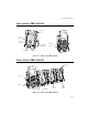
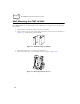
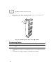
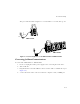
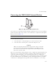
Table Of Contents
- About This Guide
- Chapter 1 Getting Started
- Chapter 2 Accessories Setup
- Chapter 3 Batch and Spectrum One Terminal Setup
- Chapter 4 Spectrum24 RF Terminal Setup
- Chapter 5 Operating the PDT 6800 Series
- Chapter 6 Maintaining the Terminal
- Chapter 7 Error Recovery and Troubleshooting
- Appendix A Null Modem Pin-outs
- Appendix B Keyboard Layouts
- Appendix C Communications Status Codes
- Appendix D Specifications
- Appendix E Boot-Up Quick Reference
- Appendix F 2D Scanner Drivers and Applications
- Numerics
- A
- B
- C
- D
- E
- F
- I
- K
- L
- M
- N
- P
- R
- S
- T
- U
- W

2-9
Accessories Setup
Connecting the CRD 38/6865 Internal Modem
Figure 2-9. RJ-11 Internal Modem Connection
Some cradles use an optional internal modem that communicates at rates of up to 14,400 bps
(with v.32 bit data compression). It can be connected directly to a telephone line through the
RJ-11 port shown in Figure 2-9.
Note:
The four-slot cradle does not have an internal modem.
To connect the internal modem:
1. Connect the phone cord into the RJ-11 port on the back of the cradle.
2. Connect the other end of the phone cord into the wall phone jack.
Caution
When connecting the internal modem to the phone line, always connect the
phone line to the cradle first, then to the wall phone jack. When removing
the connection, always remove the telephone line from the wall phone jack,
then remove from the cradle.
There are specific firmware settings which are used to configure the modem’s hardware and
software for proper operation and regulatory compliance. The terminal’s application can
control these settings and enable you to view and amend the settings for country/region,
pulse/tone dialing, or repeat dial timing. Incorrectly defining these settings can lead to illegal
use of the modem and can create unreliable operation. The application developer should
consult the Series 3000 Application Programmer’s Reference Manual for correct settings.
RJ-11
Port