
Reference Guide
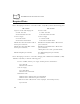
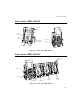
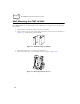
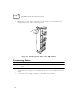
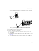
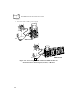
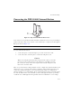
Table Of Contents
- About This Guide
- Chapter 1 Getting Started
- Chapter 2 Accessories Setup
- Chapter 3 Batch and Spectrum One Terminal Setup
- Chapter 4 Spectrum24 RF Terminal Setup
- Chapter 5 Operating the PDT 6800 Series
- Chapter 6 Maintaining the Terminal
- Chapter 7 Error Recovery and Troubleshooting
- Appendix A Null Modem Pin-outs
- Appendix B Keyboard Layouts
- Appendix C Communications Status Codes
- Appendix D Specifications
- Appendix E Boot-Up Quick Reference
- Appendix F 2D Scanner Drivers and Applications
- Numerics
- A
- B
- C
- D
- E
- F
- I
- K
- L
- M
- N
- P
- R
- S
- T
- U
- W

2-7
Accessories Setup
The green and red indicators light for 3 seconds, blink for 3 seconds, then go out.
Figure 2-7. Connecting Power to the CRD 38/6865 and CRD 38/6866
Connecting for Data Communications
To connect the CRD 38/6865 or CRD 38/6866:
1. Be sure to unplug the cradle’s power supply before connecting the serial cables.
2. Turn off the PC.
3. Plug the RS-232 serial cable’s DB-25 connector in the cradle’s communication port
(Figure 2-8).
4. Connect the cable’s other connector to the host computer’s serial (COMM) port.
CRD 38/6865
CRD 38/6866