
Reference Guide
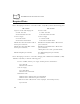
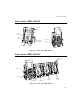
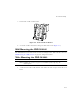
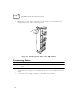
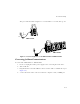
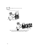
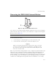
Table Of Contents
- About This Guide
- Chapter 1 Getting Started
- Chapter 2 Accessories Setup
- Chapter 3 Batch and Spectrum One Terminal Setup
- Chapter 4 Spectrum24 RF Terminal Setup
- Chapter 5 Operating the PDT 6800 Series
- Chapter 6 Maintaining the Terminal
- Chapter 7 Error Recovery and Troubleshooting
- Appendix A Null Modem Pin-outs
- Appendix B Keyboard Layouts
- Appendix C Communications Status Codes
- Appendix D Specifications
- Appendix E Boot-Up Quick Reference
- Appendix F 2D Scanner Drivers and Applications
- Numerics
- A
- B
- C
- D
- E
- F
- I
- K
- L
- M
- N
- P
- R
- S
- T
- U
- W

2-2
PDT 6800 Series Product Reference Guide
Required Parts
Before attempting to mount or connect the cradles, verify that you have the following parts:
Before attempting to mount or connect the Charging and Communications Module (CCM)
38/6860, verify that you have the following parts:
CRD 38/6865 CRD 38/6866
Single-Slot Cradle with Charging Slot:
!
US Kit: 3865-110
!
International Kit: 3865-111
Four-Slot Cradle
!
US Kit: 3866-100
!
International Kit: 3866-101
AC Power Supply:
!
US:59915-00-00
!
International: 60507-00-00
AC Power Supply
!
US:60153-00-00
!
International: 60174-00-00
Null Modem Cable, DB 25 Male to DB 25
Female (p/n 25-19297-01)
Null Modem Cable, DB25 Male to DB 9
Female (p/n 25-19299-01)
Null Modem Cable, DB 25 Male to DB 25 Female
(p/n 25-19297-01)
Null Modem Cable DB25 Male to DB 9 Female
(p/n 25-19299-01)
Chaining Interconnect Cable (p/n 60427-00-00)
Wall Mounting Kit (p/n 3866-000) Two Wall Mounting Kits (p/n 3866-000)
per 38/6866
Four-slot CCM Kit (includes power supply, mounting brackets, and hardware:
!
US: 3860-100
!
International: 3860-101
AC Power Supply:
!
US: 58690-00-00
!
International: 58690-01-00
Null Modem Cable
!
DB-25 Female to DB-25 Female (p/n 59846-00-00)
!
DB-25 Female to DB-9 Female (p/n 25-19298-01)
CCM Four-Slot Add-on Kit (includes CCM, coupling kit, and mounting brackets):
!
p/n 3861-101