
Reference Guide
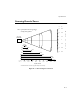

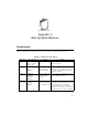
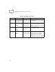
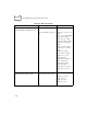
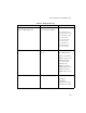
Table Of Contents
- About This Guide
- Chapter 1 Getting Started
- Chapter 2 Accessories Setup
- Chapter 3 Batch and Spectrum One Terminal Setup
- Chapter 4 Spectrum24 RF Terminal Setup
- Chapter 5 Operating the PDT 6800 Series
- Chapter 6 Maintaining the Terminal
- Chapter 7 Error Recovery and Troubleshooting
- Appendix A Null Modem Pin-outs
- Appendix B Keyboard Layouts
- Appendix C Communications Status Codes
- Appendix D Specifications
- Appendix E Boot-Up Quick Reference
- Appendix F 2D Scanner Drivers and Applications
- Numerics
- A
- B
- C
- D
- E
- F
- I
- K
- L
- M
- N
- P
- R
- S
- T
- U
- W

D-3
Specifications
Scanning Decode Zones
Figure D-1. 1D Scanning Decode Zones
In.
cm
0
0
5
12.7
10
25.4
15
38.1
20
50.8
25
63.5
30
76.2
35
88.9
Minimum distance determined by symbol length and scan angle
0
5
10
15
5
10
In. cm
W
i
d
t
h
o
f
F
i
e
l
d
Depth of Field
Note: Typical performance at 68 F (20 C)
on high quality symbols.
40
101.6
45
114.3
15
5 mil
6.0
4.0
7.5 mil
9.0
2.5
SE 1200
STANDARD
10 mil
14.0
2.5
15 mil
25.0
2.5
20 mil
28.0
*
*
40 mil
40.0
*
55 mil
41.0
*
0
12.7
25.4
38.1
12.7
25.4
38.1