
User Manual


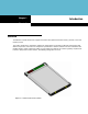
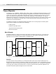
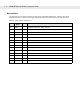
Table Of Contents
- MR400 RFID Reader Module
- Table of Contents
- About
- MR400 Integration GuideIntroduction
- InstallationMR400 RFID Reader Module, Integration GuideInstallation
- MR400 RFID Reader Module, Integration Guide
- MR400 RFID Reader Module, Integration GuideMR400 SpecificationsMR400 Specifications
- Regulatory InformationRegulatory InformationMR400 RFID Reader Module, Integration Guide
- Index

1 - 4 MR400 RFID Reader Module, Integration Guide
Host Interface
The host interface connector consists of a PCB connector p/n Molex 54548-1470, 0.50mm (.020") pitch
FFC/FPC connector, 1.20mm (.047") height, right angle, SMT, ZIF, bottom contact style, with 14 circuits.
Table 1-1
Host Interface Connector J1
Pin #
Signal
Names
Dir
Description
1
+5Vdc I Regulated +5Vdc (4V - 5.5V), 2A max,
2
+5Vdc I Regulated +5Vdc (4V - 5.5V), 2A max,
3
+5Vdc I Regulated +5Vdc (4V - 5.5V), 2A max,
4
WAKE I wake reader up from sleep mode
5
READY O reader is ready to accept command
6
GPIO_1 IO General purpose input or output, 3.3V TTL, user configurable, default to input
7
GND I Ground
8
RESET_N I reset reader to default state
9
GPI_2 IO General purpose input or output, 3.3V TTL, user configurable, default to input
10
GPIO_3 IO General purpose input or output, 3.3V TTL, user configurable, default to input
11
GND I Ground
12
TTL_TX O
•
3.3V TTL Serial Transmit Data, 5V tolerant,
13
TTL-RX I
•
3.3V TTL Serial Receive Data, 5V tolerant,
14
GND I
•
Ground