MR 100 User Manual MR 100 User Manual Symbol Technologies Inc., 7361 Calhoun Place, Suite 250 Rockville, MD 20855 Phone: (301) 610-6100 Fax: (301) 610-6101 http://www.symbol.com Document Version: Version 1.
MR 100 User Manual Notices Copyright © 2004 Symbol, Inc. All rights reserved. This document is protected by copyright with all rights reserved. No part of the document may be reproduced or transmitted by any means or in any form without prior consent in writing from Symbol, Inc. Trademarks Symbol is a registered trademark of Symbol, Inc. All other product names or logos mentioned herein are used for identification purposes only, and are the trademarks of their respective owners.
MR 100 User Manual Table of Contents Chapter 1. Introduction .................................................................................................................. 4 1.1. Scope............................................................................................................................... 4 1.1.1. Target Audience ............................................................................................................... 4 1.1.2. Assumptions....................................
MR 100 User Manual A. Hardware and Technical Specifications ..........................................................................................14 A.1. Physical Dimensions ............................................................................................................ 14 A.2. Power ............................................................................................................................. 14 A.3. Environmental .........................................................
MR 100 User Manual C h a p t e r 1 . I N T R O D U C T I O N 1.1. Scope The Symbol MR100 Reader User Manual provides the following information pertaining to Symbol MR100 Receiver Module: Hardware Specifications and details. Supported API calls. 1.1.1. Target Audience This guide is targeted for developers who will be writing code that interfaces with MR 100 reader using the Byte Stream Protocol. 1.1.2.
MR 100 User Manual 1.3. Document Conventions The following Conventions have been used in this Guide: Document Convection Bulleted List 1. Numbered List Version Provides Grouped Action and non procedural steps Procedural steps for performing an action. A Note / Focus point that the reader might be interested in knowing. A Warning Note. A Caution Note. 1.4.
MR 100 User Manual C h a p t e r A N 2 . I N T R O D U C T I O N T O M R 1 0 0 The Symbol RF Receiver Module or MR 100 is a single port, lightweight reader designed for easy integration with RFID printers, handhelds and applicators1. This chapter describes some of the important features of MR 100. 2.1. MR 100 Features 2.1.1.
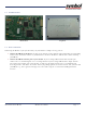
MR 100 User Manual 2.3. Product Pictures Board View Top View 2.4. Basic Connections Connecting the MR 100 to your system is fairly easy and includes a simple two step process: Connect the MR 100 to the device you plan to use with the reader using the JST 14-Pin Connector. Depending on the device you wish to connect to you should select between the RS 232 / TTL interfaces before ordering your MR 100.
MR 100 User Manual B Y T E C h a p t e r 3 . S T R E A M P R O T O C O L W I T H M R 1 0 0 This chapter gives a brief introduction to Byte Stream Protocol and how it can be used to communicate with the MR 100 reader. If you are looking for more details of Byte Stream Protocol and how it can be used with other Symbol Readers refer to Matrics API Programmers Manual. 3.1.
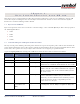
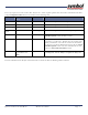
MR 100 User Manual For every request sent to the reader there may be one / more response packets that the reader sends back to the host. A Typical Response Packet has been described in the following table: Field Number of Bytes (Size) Value Description SOF 1 0x01 Described in Request Packet description. Node Address 1 0~0x1F Described in Request Packet description. Packet Length 1 See Description Described in Request Packet description.
MR 100 User Manual B Y T E C h a p t e r 4 . S T R E A M C O M M A N D L I S T Below is a listing of all commands that are supported by the MR 100 reader. For more information of how to use each command refer to the Matrics API Programmers Manual. 4.1. Read Full Field Command (22hex) Read all RFID tags using one antenna port of the addressed reader. With the MR 100 you can use this command to read tags using the first and only antenna port of the reader.
MR 100 User Manual 4.9. Read With Payload Command (31hex) Only the first antenna port must be passed in the request packet while using this command with the MR 100 reader. No Antenna combination options should be used with this command when using it with the MR 100 since the MR 100 does not support combination of antennas. For more information on this command refer to the Matrics API Programmers Manual. 4.10.
MR 100 User Manual Index 12hex .......................................................10 31hex ...................................................... 11 14hex .......................................................10 32 18hex .......................................................10 33hex ...................................................... 11 19hex .......................................................10 EPC .........................................................5 1Chex ......................
MR 100 User Manual Device Specifications Device Specifications MR 100 User Manual Page: 13
MR 100 User Manual A. HARDWARE AND TECHNICAL SPECIFICATIONS This section describes in details the specifications of hardware interfaces that are used with Symbol MR-100 Readers. A.1. Physical Dimensions Dimensions Length 3.4” x Width 2.1” x Height 0.3” (85.6 mm x 54 mm x 8 mm) Weight ~ 2.5 Ounces (70 Grams) Visual Status Indicator On-board LED for Radio On/Off indication A.2. Power Power Supply +6vDC @ 1.2 Amp (Regulated) Operational Power Consumption 4.
MR 100 User Manual A.5. Interface Pin Outs Pin Number Signal Dir Description Pin 1: VIN I Regulated +6Vdc (min/max 5.4v/7v), 1.2A max, 2A fused Pin 2: VIN I Regulated +6Vdc (min/max 5.4v/7v), 1.2A max, 2A fused Pin 3: GND I Ground Pin 4: GND I Ground Pin 5: GPIO_1 I/O General purpose input or output #1, 3.3V TTL, configurable via board stuff-in option, default to input. Pin 6: GPIO_2 I/O General purpose input or output #2, 3.
MR 100 User Manual B. PHYSICAL DIMENSIONS This section provides detailed diagram physical dimensions of the MR 100. B.1. Top View B.2.
MR 100 User Manual B.3. Bottom View Note: Unit Of Measurement used in above diagrams is inches.
MR 100 User Manual C. COMPLIANCE & REGULATORY INFORMATION All Symbol devices are designed to be compliant with rules and regulations in locations they are sold and will be labeled as required. Any changes or modifications to Symbol Technologies equipment, not expressly approved by Symbol Technologies, could void the user’s authority to operate the equipment. Antennas: Use only the supplied or an approved replacement antenna.
MR 100 User Manual determined by turning the equipment off and on, the user is encouraged to try to correct the interference by one or more of the following measures: • Reorient or relocate the receiving antenna • Increase the separation between the equipment and receiver • Connect the equipment into an outlet on a circuit different from that to which the receiver is connected • Consult the dealer or an experienced radio/TV technician for help. C.5.
MR 100 User Manual United States This module is approved for integration; to maintain the approval the integrator must address the following: • FCC Part 15 (emissions class B) required for the final product • SAR testing required on final product (Note: If final product, in normal usage, is operated more than 20cm from the human body, MPE testing is required instead of SAR) Final product markings must include: • Contains FCC ID: H9PMR100A Canada In complying with the requirements for the FCC, this device