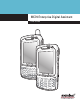
MC70 Enterprise Digital Assistant User Guide
MC70 User Guide 72E-71769-01 Revision B August 2006
ii MC70 User Guide © 2006 by Symbol Technologies, Inc. All rights reserved. No part of this publication may be reproduced or used in any form, or by any electrical or mechanical means, without permission in writing from Symbol. This includes electronic or mechanical means, such as photocopying, recording, or information storage and retrieval systems. The material in this manual is subject to change without notice. The software is provided strictly on an “as is” basis.
iii Revision History Changes to the original manual are listed below: Change Date Description A 1/2006 Initial release. B 8/2006 Add Revision History page. Chapter 2: Add vibrator feature information. Remove Green and Red Phone button remapping information. Not supported. Update cold boot procedure to remove step to calibrate screen after cold boot.
iv MC70 User Guide
Table of Contents Patents........................................................................................................................... ii Revision History ............................................................................................................. iii About This Guide Introduction .................................................................................................................... xi Documentation Set ...........................................................
vi MC70 User Guide Turning Off the WLAN Radio ............................................................................ 1-12 Turning Off the Bluetooth and WAN Radios ..................................................... 1-13 Chapter 2: Using the MC70 Introduction ................................................................................................................... Status Icons .................................................................................................................
Table of Contents - vii Modes ........................................................................................................................... 3-4 Wizard Mode ........................................................................................................... 3-4 Explorer Mode ......................................................................................................... 3-6 Discovering Bluetooth Device(s) .........................................................................
viii MC70 User Guide Taking Notes ................................................................................................................. Using Speed Dial .......................................................................................................... Adding a Speed Dial Entry ...................................................................................... Editing a Speed Dial Entry ......................................................................................
Table of Contents - ix Magnetic Stripe Reader (MSR) ..................................................................................... 5-12 Attaching and Removing the MSR .......................................................................... 5-12 Using the MSR ....................................................................................................... 5-13 TRG7000 Trigger Handle ..............................................................................................
x MC70 User Guide
About This Guide About This Guide Introduction This guide provides information about using the MC70 Enterprise Digital Assistant (EDA) and accessories. NOTE Screens and windows pictured in this guide are samples and can differ from actual screens. Documentation Set The documentation set for the MC70 provides information for specific user needs, and includes: • Microsoft® Windows Mobile 5.0 Applications User Guide for Symbol Devices - describes how to use Microsoft developed applications.
xii MC70 User Guide Configurations This guide covers the following configurations: • MC7004 - Windows® Mobile 5.0 Operating System; EDGE GPRS quad-band WAN radio; Bluetooth® wireless technology (Class II); QVGA 3.5” color display; 64MB RAM/128MB flash memory; 1D laser scanner or 2D imager; numeric or QWERTY keypad; VoIP ready (VoIP application does not ship with the EDA); user accessible SD card slot. • MC7090 - Windows® Mobile 5.0 Operating System; 802.
About This Guide xiii Chapter Descriptions Topics covered in this guide are as follows: • Chapter 1, Getting Started provides information on getting the EDA up and running for the first time. • Chapter 2, Using the MC70 provides basic instructions for using the EDA, including powering on and resetting the EDA, and entering and capturing data. • Chapter 3, Using Bluetooth explains Bluetooth functionality on the EDA.
xiv MC70 User Guide Related Documents • MC70 Quick Start Guide, p/n 72-71770-xx • MC70 Microsoft Mobile 5.0 Regulatory Information, p/n 72-71767-xx • MC70 Integrator Guide, p/n 72E-71768-xx • Microsoft® Applications for Mobile and CE 5.0 User Guide, p/n 72E-78456-xx • Symbol Application Guide, p/n 72E-68901-xx • Symbol Mobility Developer Kits (SMDKs), available at: http://devzone.symbol.com/. • Latest ActiveSync software, available at: http://www.microsoft.com.
About This Guide Country/Region Address Telephone Asia/Pacific Symbol Technologies Asia, Inc. (Singapore Branch) 230 Victoria Street #12-06/10 Bugis Junction Office Tower Singapore 188024 Tel: +65-6796-9600 Fax: +65-6337-6488 Australia Symbol Technologies Pty. Ltd. 432 St. Kilda Road Melbourne, Victoria 3004 Australia 1-800-672-906 (Inside Australia) +61-3-9866-6044 (Outside Australia Austria/Österreich Symbol Technologies Austria GmbH Prinz-Eugen Strasse 70 / 2.
xvi MC70 User Guide Country/Region Address Telephone Norway/Norge Symbol’s registered and mailing address: Symbol Technologies Norway Hoybratenveien 35 C N-1055 OSLO, Norway Symbol’s repair depot and shipping address: Symbol Technologies Norway Enebakkveien 123 N-0680 OSLO, Norway +47 2232 4375 South Africa Symbol Technologies Africa Inc.
Getting Started Chapter 1 Chapter 1 Getting Started Introduction This chapter lists the parts and accessories for the EDA and explains how to install and charge the batteries, replace the strap, and power on the EDA for the first time.
1-2 MC70 User Guide Handstrap Battery Cover Handstrap Slot Battery Cover Latch Headset Jack Memory Card Slot Speaker Scan Window (Imager Model Shown) Action Button Scan/Action Button Tether Point Stylus Figure 1-2 MC70 Rear View Unpacking Carefully remove all protective material from the EDA and save the shipping container for later storage and shipping.
Getting Started 1-3 Accessories Table 1-1 lists the accessories available for the MC70 EDA. Table 1-1 MC70 Accessories Accessory Snap-on Cables Description The EDA supports the following cables: • AC line cord (country-specific) and power supply, charges the EDA. • Auto charge cable, charges the EDA using a vehicle’s cigarette lighter. • DEX cable, connects the EDA to a vending machine. • Serial cable, adds serial communication capabilities. • USB cable, adds USB communication capabilities.
1-4 MC70 User Guide Getting Started To start using the EDA for the first time: • Install the main battery and cover assembly. • Charge the EDA. • Power on the EDA. • Configure the EDA. Installing and Removing the Main Battery Installing the Main Battery Before using the EDA, install a lithium-ion battery. The standard capacity 1900 mAh battery is shown. The extended capacity 3800 mAh battery requires a larger capacity battery cover. 1.
Getting Started 3. 1-5 With the battery cover latches open, insert the cover, bottom first, then press down on the top of the cover. Battery Cover Latch Battery Cover Figure 1-4 Inserting the Battery Cover 4. Close the battery cover latches on either side of the battery cover. 5. Insert the handstrap through the handstrap slot, then tighten and press down to secure. Handstrap Handstrap Slot Figure 1-5 Inserting the Handstrap The EDA powers up after inserting the battery.
1-6 MC70 User Guide Lift the top of the battery cover and remove. 4. Figure 1-7 Removing the Battery Cover Press the battery release latch on the bottom of the battery to unlock, and lift the battery out of the well. 5. Charging the Battery Charging the Main Battery and Memory Backup Battery Before using the EDA for the first time, charge the main battery until the amber Charge Status LED remains lit (see Table 1-2 on page 1-7 for charge status indications).
Getting Started 1-7 The standard capacity battery (1900 mAh) fully charges in less than four hours. The extended capacity battery (3800 mAh) fully charges in less than eight hours. Table 1-2 LED Charge Indicators Charge Status LED Indication Off EDA is not charging; EDA is not inserted correctly in the cradle or connected to a power source; charger is not powered. Slow Blinking Amber (1 blink every 2 seconds) EDA is charging. Solid Amber Charging complete.
1-8 MC70 User Guide Charging Temperature Charge batteries in temperatures from 0oC to 40oC (32°F to 104°F). Note that at temperatures above 35oC, charging is intelligently controlled by the EDA and the charging accessory in order to ensure safe operation and optimize long-term battery life. To accomplish this, for small periods of time, the EDA or accessory alternately enables and disables battery charging to keep the battery at acceptable temperatures.
Getting Started 1-9 SIM Card NOTE MC7004 and MC7094 only. GPRS phone service requires a Subscriber Identification Module (SIM) card, or smart card. Obtain this card from the phone service provider. The card fits into the EDA and can contain the following information: • Mobile phone service provider account details. • Information regarding service access and preferences. • Contact information, which can be moved to Contacts on the EDA. • Any additional services to which you have subscribed.
1 - 10 MC70 User Guide 7. Press the red Power button. 8. Tap Start - Phone - Menu - Options - Network tab and verify that the service provider appears in the Current network: field. 9. Make a call to verify connection. NOTE For detailed information about WWAN activation and settings, refer to the MC70 Integrator Guide. Adjusting the Handstrap The EDA handstrap is attached to the bottom of the battery cover. Adjust the handstrap to increase comfort when holding the EDA for extended periods of time.
Getting Started 1 - 11 Removing the Screen Protector A screen protector is applied to the MC70. Symbol recommends using this to minimize wear and tear. Screen protectors enhance the usability and durability of touch screen displays. To remove the screen protector, lift the corner using a thin plastic card, such as a credit card, then carefully lift it off the display. Lift Screen Protector Corner Figure 1-11 Removing the Screen Protector CAUTION Do not use a sharp object to remove the protector.
1 - 12 MC70 User Guide Changing the Power Settings To set the EDA to turn off after a short period of non-use: 1. Tap Start - Settings - System tab - Power icon - Advanced tab. 2. Select the On battery power: Turn off device if not used for check box and select a value from the drop-down list. 3. Select ok. Changing the Backlight Settings To change the backlight settings in order to conserve more battery power: 1. Tap Start - Settings - System tab - Backlight icon - Battery Power tab. 2.
Getting Started 1 - 13 Turning Off the Bluetooth and WAN Radios NOTE The Flight Mode feature only turns off the WAN and Bluetooth radios. You must turn off the WLAN radio separately. To turn off the Bluetooth and WAN radios: • Tap the Connectivity icon (on non-WAN devices) or the Antenna/Signal icon devices) and select Turn on flight mode (on WAN OR • Tap the Bluetooth icon and select Disable Bluetooth.
1 - 14 MC70 User Guide
Using the MC70 Chapter 2 Chapter 2 Chapter 2 Using the MC70 Introduction This chapter explains the buttons, status icons, and controls on the EDA, and provides basic instructions for using the EDA, including powering on and resetting the EDA, and entering and capturing data. Status Icons The navigation bar at the top of the screen can contain the status icons listed in Table 2-1. Table 2-1 Status Icons Icon Function Speaker Description All sounds are on. All sounds are off. Vibrate is on.
2-2 MC70 User Guide Table 2-1 Status Icons (Continued) Icon Function WWAN Description Call missed. Voice call. Voice call in progress. Calls are forwarded. Call on hold. Speakerphone is on. Antenna/signal icon: wireless on/good signal. Antenna/signal icon: wireless off. Antenna/signal icon: no service or searching. Roaming. Time and Next Appointment Displays current time in analog or digital format. Instant Message Notification that one or more instant messages were received.
Using the MC70 2-3 The command bar at the bottom of the screen can contain the task tray icons listed in Table 2-2. Table 2-2 Task Tray Icons Icon Description Wireless connection status Indicates WLAN signal strength. Bluetooth Enabled Bluetooth radio is on. Bluetooth Disabled Bluetooth radio is off. ActiveSync Active connection between the EDA and the development PC. Speaker Icon To adjust the system volume using the Speaker icon in the navigation bar: 1. Tap the Speaker icon.
2-4 MC70 User Guide Battery Icon Battery icons appear on the navigation bar when the main battery or backup battery power falls below a predetermined level. A Battery dialog box also appears indicating the status of the main or backup battery. Figure 2-2 Battery Status Dialog Box Also view the battery status using the Power window. Connectivity Icon The Connectivity icon indicates the communication status of the EDA when it is connecting to the internet or host computer.
Using the MC70 2-5 WWAN Icon The WWAN icons indicate the status of the phone and antenna/signal. Call in Progress Figure 2-4 WWANConnectivity Icon Time Icon The Time icon displays the current time in a digital or analog format. To change the time format, tap and hold the Time icon until a menu appears. Select the format.
2-6 MC70 User Guide To display current date, time, and appointments, tap the Time icon to display the Time and Next Appointment dialog box. Battery Status Icon Upcoming Appointments Current Date and Time Figure 2-6 Time and Next Appointment Dialog Box The dialog box displays the current date and time, the battery status, and any upcoming appointments in the Calendar. Instant Message Icon The Instant Message icon notifies you when MSN Messenger receives a new message.
Using the MC70 2-7 E-Mail Icon The E-Mail icon notifies you when you receive incoming e-mails. Figure 2-8 New E-mail Messages Dialog Box Multiple Notifications Icon The Multiple Notifications icon appears when two or more message notifications occur. Tap the icon to display the multiple notification icons.
2-8 MC70 User Guide LED Indicators The MC70 has three LED indicators. The Scan/Decode LED indicates status for scanning. The Charge Status LED indicates status for main battery charging. The Radio Power Status LED indicates radio status. Table 2-3 describes the LED indications. Scan/Decode LED Charge Status LED Radio Power Status LED Figure 2-10 LED Indicators Table 2-3 LED Indications LED State Indication Scan/Decode LED Solid Green Successful decode/capture.
Using the MC70 2-9 Keypads The EDA offers two modular keypad configurations: Numeric and QWERTY. Numeric Keypad Configuration The numeric keypad contains application keys, scroll keys, and function keys. The keypad is color-coded to indicate the alternate function key (blue) values. Note that an application can change keypad functions so the EDA’s keypad may not function exactly as described. See Table 2-4 for key and button descriptions and Table 2-5 on page 2-11 for the keypad’s special functions.
2 - 10 MC70 User Guide Table 2-4 MC70 Numeric Keypad Descriptions Key Blue Key (left) Description Use this key to launch applications or access items (shown on the keypad in blue). Press the Blue key once to activate this mode, followed by another key. A single press displays the following icon at the bottom of the screen, until a second key is pressed: Orange Key (right) Use this key to access the secondary layer of characters and actions (shown on the keypad in orange).
Using the MC70 2 - 11 Table 2-4 MC70 Numeric Keypad Descriptions (Continued) Key Description Alphanumeric In default state, produces the numeric value on the key. In Alpha state, produces the lower case alphabetic characters on the key. Each key press produces the next alphabetic character in sequence. For example, press and release the Orange key and then press the ‘4’ key once to produce the letter ‘g’; press and release the Orange key and then press the ‘4’ key three times to produce the letter ‘i’.
2 - 12 MC70 User Guide Table 2-5 Numeric Keypad Input Modes (Continued) Orange Key (Alpha Lowercase Mode) Numeric Mode Orange + Shift Keys (Alpha Uppercase Mode) Key Blue+ Key SHIFT + Key 1st Press 2nd Press 3rd Press 4th Press 1st Press 2nd Press 3rd Press 4 4 F4 $ g h i G H I 5 5 F5 % j k l J K L 6 6 F6 ^ m n o M N O 7 7 F7 & p q r P Q R 8 8 F8 * t u v T U V 9 9 F9 ( w x y W X Y 0 0 F10 ) .
Using the MC70 2 - 13 QWERTY Keypad Configuration The QWERTY keypad produces the 26-character alphabet (A-Z, both lowercase and uppercase), numbers (0-9), and assorted characters. The keypad is color-coded to indicate which modifier key to press to produce a particular character or action. The keypad default is alphabetic, producing lowercase letters. See Table 2-6 for key and button descriptions and Table 2-7 on page 2-15 for the keypad’s special functions.
2 - 14 MC70 User Guide Table 2-6 QWERTY Keypad Descriptions (Continued) Key Orange Key (right) Action Accesses the secondary layer of characters and actions (shown on the keypad in orange). • Press the Orange key once to activate this mode temporarily, followed by another key. This displays the following icon at the bottom of the screen, until a second key is pressed: • Press the Orange key twice to lock this mode.
Using the MC70 2 - 15 Table 2-6 QWERTY Keypad Descriptions (Continued) Key Action Backlight Turns the display backlight on and off. Backspace Produces a backspace. Enter Executes a selected item or function. Star Produces an asterisk. OK Use this key in conjunction with the Blue key as an OK or close button. This function is user programmable. Start Menu Use this key in conjunction with the Blue key to instantly display the Start menu from any application without tapping the screen.
2 - 16 MC70 User Guide Table 2-7 QWERTY Keypad Input Modes (Continued) Key Normal Shift + Key Orange + Key I i I = O o O “ P p P áü A a A # S s S 4 D d D 5 F f F 6 G g G ( H h H ) J j J / K k K : L l L ‘ BACKSPACE Backspace Shift Shift Z z Z 7 X x X 8 C c C 9 V v V % B b B & N n N ! M m M ? , , < @ TAB Tab SPACE Space . .
Using the MC70 2 - 17 Special Character Key NOTE Special characters are only available on the QWERTY keypad configurations. To add special characters using the MC70 áü key, type the related character first, then press the Orange + áü (P) key. Continue holding the Orange key and pressing the áü key until the special character displays.
2 - 18 MC70 User Guide Table 2-8 Special Characters (Continued) Key T u U y Y z Z $ / “ ( ) + ! .
Using the MC70 2 - 19 Function Buttons The EDA’s buttons perform certain functions. Power Button Scan/Action Button Up/Down Button Action Button Scan/Action Button Figure 2-13 Function Buttons • Power: Press the red Power button to turn the EDA screen on and off. The EDA is in suspend mode when the screen is off. For more information, see Powering On the EDA on page 1-8. Also use the Power button to reset the EDA by performing a warm or cold boot. See Resetting the EDA on page 2-24.
2 - 20 MC70 User Guide ! CAUTION stylus. To prevent damage to the screen, do not use any device other than the Symbol-provided Using a Headset You can use a stereo headset for audio communication when using an audio-enabled application. To use a headset, plug the headset jack into the audio connector on the side of the EDA. Set the EDA’s volume appropriately before putting the headset on. Plugging a headset into the jack mutes the speaker. For the best audio performance, symbol recommends a 2.
Using the MC70 2 - 21 Linear Scanning EDAs with an integrated linear scanner have the following features: • Reading of a variety of bar code symbologies, including the most popular linear, postal, and 1-D code types. • Intuitive aiming for easy point-and-shoot operation. Imaging EDAs with an integrated imager have the following features: • Omnidirectional reading of a variety of bar code symbologies, including the most popular linear, postal, PDF417, and 2D matrix code types.
2 - 22 MC70 User Guide • Angle Scanning angle is important for promoting quick decodes. When laser beams reflect directly back into the scanner from the bar code, this specular reflection can “blind” the scanner. To avoid this, scan the bar code so that the beam does not bounce directly back. But don’t scan at too sharp an angle; the scanner needs to collect scattered reflections from the scan to make a successful decode. Practice quickly shows what tolerances to work within.
Using the MC70 2 - 23 Imager Scanning 1. Ensure that a scan-enabled application is loaded on the EDA. 2. Aim the scan window at the bar code. Figure 2-18 Imager Scanning 3. Press the scan button. The red laser aiming pattern turns on to assist in aiming. Ensure the bar code is within the area formed by the brackets in the aiming pattern.
2 - 24 MC70 User Guide Figure 2-21 Pick List Mode with Multiple Bar Codes in Aiming Pattern 4. Release the scan button. NOTE Imager decoding usually occurs instantaneously. The EDA repeats the steps required to take a digital picture (image) of a poor or difficult bar code as long as the scan button remains pressed. Resetting the EDA There are two reset functions, warm boot and cold boot. A warm boot restarts the EDA by closing all running programs.
Using the MC70 2 - 25 Waking the EDA The wakeup conditions define what actions wake up the EDA. These settings are configurable and the factory default settings shown in Table 2-9 are subject to change/update. Table 2-9 Wakeup Conditions (Default Settings) Status Power Off (Suspend Mode) Description When the EDA suspends by pressing Power, these actions wake the EDA. Conditions for Wakeup 1. Power button is pressed. 2. AC power added or removed. 3. Cradle/cable connect or disconnect.
2 - 26 MC70 User Guide To unlock the device and free it for use, tap Unlock. Figure 2-23 Unlock Device Window Tap Unlock on the Unlock Device window.
Chapter 3 Using Bluetooth Chapter 3 Using Bluetooth Introduction Bluetooth-equipped devices can communicate without wires, using frequency-hopping spread spectrum (FHSS) radio frequency (RF) to transmit and receive data in the 2.4 GHz Industry Scientific and Medical (ISM) band (802.15.1). Bluetooth wireless technology is specifically designed for short-range (30 feet/10 meters) communication and low power consumption. EDAs with Bluetooth capabilities can exchange information (e.g.
3-2 MC70 User Guide Security The current Bluetooth specification defines security at the link level. Application-level security is not specified. This allows application developers to define security mechanisms tailored to their specific need. Link-level security occurs between devices, not users, while application-level security can be implemented on a per-user basis.
Using Bluetooth 3-3 Disabling Bluetooth To disable Bluetooth, tap Bluetooth icon - Disable Bluetooth. The Bluetooth icon changes to indicate that Bluetooth is disabled. Figure 3-1 Disable Bluetooth Enabling Bluetooth To enable Bluetooth, tap Bluetooth icon - Enable Bluetooth. The Bluetooth icon changes to indicate that Bluetooth is enabled.
3-4 MC70 User Guide Warm Boot Performing a warm boot on the EDA returns Bluetooth to the last state after initialization. Suspend Suspending the EDA turns off Bluetooth. NOTE Suspending the EDA powers off the Bluetooth radio and drops the piconet (Bluetooth connection). When the EDA resumes, it take approximately 10 seconds for the Bluetooth radio driver to re-initialize the radio. Resume When the EDA resumes, Bluetooth turns on if it was on prior to suspend.
Using Bluetooth Select an action from the drop-down list. Options include: 3. • Explore Services on Remote Device • Pair with a Remote Device • Active Sync via Bluetooth • Browse Files on Remote Device • Connect to Headset • Connect to Internet Using Access Point • Connect to Internet Using Phone/Modem • Connect to a Personal Area Network • Send or Exchange Objects • Associate Serial Port.
3-6 MC70 User Guide 6. Select the Save As Favorite check box to save this service in the Favorite view. 7. In the Favorite Name text box, enter a name for this service that will appear in the Favorite list. 8. Tap Next. The Connection Summary window appears. Figure 3-6 Connection Summary Window 9. Tap Connect to connect to the service. Explorer Mode The Explorer Mode window is easy to navigate and provides greater control to users familiar with Bluetooth.
Using Bluetooth 3-7 You can also use the “tap and hold” technique to view available options. Scroll bars and view options are similar to those on the Windows desktop. The tree structure lists the following sub-items: • Local Device - This EDA • Remote Device - Other Bluetooth devices - Trusted Devices - Bonded (paired) Bluetooth devices - Untrusted Devices - Discovered devices that are not bonded • Favorites - Selected services that are set as Favorite for quick access.
3-8 MC70 User Guide 4. Tap and hold Remote Devices and select Discover Devices from the pop-up menu. The EDA searches for Bluetooth devices in the area. Figure 3-9 Discover Devices The discovered devices display in the Untrusted Devices folder. Figure 3-10 Discovered Devices Listed in Untrusted Folder Bonding with Discovered Device(s) A bond is a relationship created between the EDA and another Bluetooth device in order to exchange information in a secure manner.
Using Bluetooth To bond with a discovered Bluetooth device: 1. Discover remote devices. See Discovering Bluetooth Device(s) on page 3-7. 2. In the Untrusted Devices folder, tap and hold on a device to pair with. Figure 3-11 Pairing a Remote Device 3. Select Pair from the pop-up menu. The PIN Code Request window appears. Figure 3-12 PIN Code Request Window 4. In the PIN Code: text box, enter the PIN number (between 1 and 16 characters) and then tap OK. 5.
3 - 10 MC70 User Guide 6. The devices pair and the device name moves to the Trusted Devices folder. Figure 3-13 Bonded (Paired) Discovered Device Renaming a Bonded Device To rename a bonded device: 1. Launch BTExplorer. 2. Tap and hold the device to rename.
Using Bluetooth 3 - 11 3. Select Rename in the pop-up menu. The Change Device Name window appears. Figure 3-15 Change Device Name Window 4. Enter a new name for the bonded device in the text box. Tap OK. Deleting a Bonded Device To delete a device no longer needed: 1. Launch BTExplorer. 2. Tap and hold the device to delete and select Delete in the pop-up menu. Figure 3-16 Deleting a Bonded Device 3. A confirmation dialog appears. Tap Yes.
3 - 12 MC70 User Guide Accepting a Bond When a remote device wants to bond with the EDA, enter a PIN when requested to grant permission. 1. Ensure that the EDA is set to discoverable and connectable. See Bluetooth Settings on page 3-25. When prompted to bond with the remote device the PIN Code Request window appears. Figure 3-17 PIN Code Request Window 2. In the PIN Code: text box, enter the same PIN entered on the device requesting the bond. The PIN must be between 1 and 16 characters. 3.
Using Bluetooth 3 - 13 The EDA communicates with the remote device and lists the services under the device name. Figure 3-19 List of Discovered Services Some examples of available services are: • File Transfer Services • Dial-Up Networking Services • OBEX Object Push Services • Headset or Hands-Free Services • Serial Port Services. See the following sections for information on these services. File Transfer Services To transfer files between the EDA and another Bluetooth enabled device: 1.
3 - 14 MC70 User Guide Select a folder. The contents of the folder appear in the sub-window. 8. Figure 3-20 Remote Device Folders Tap and hold on the file. A pop-up menu appears. 9. 10. Select the action to perform: • New - create a new file or folder on the remote device • Delete - delete the selected file on the remote device. • Get File - copy the file from the remote device to the EDA. • Put File - copy a file from the EDA to the remote device.
Using Bluetooth 3 - 15 Copying a File To copy a file to a remote device: 1. Tap and hold on the file and select Put. The Send Local File window appears. 2. Navigate to the directory to save the file and select a file. 3. Tap Open. The file copies from the EDA to the remote device. Connecting to the Internet Using an Access Point This section explains how to access a Bluetooth-enabled LAN access point (AP) for a network connection. Use Internet Explorer to connect to a server. 1.
3 - 16 MC70 User Guide Before setting up dial-up networking, obtain dial-up information and other necessary settings for the office network or ISP. To create a new Bluetooth connection: 1. Ensure the EDA is discoverable and connectable. See Bluetooth Settings on page 3-25. 2. Discover and bond (pair) with the remote device. See Bonding with Discovered Device(s) on page 3-8. 3. In BTExplorer, select the Remote Devices folder. 4. Select the Trusted Devices folder. 5. Tap the remote device folder.
Using Bluetooth 3 - 17 10. In the User name: text box, enter the user name for this connection. 11. In the Password: text box, enter the password for this connection. 12. In the Domain: text box, enter the domain for this connection, if required. 13. Tap OK. The phone begins dialing, then connects to the network. Figure 3-23 Connecting to Bluetooth Phone 14. To end a session, tap the Connection icon and then tap Disconnect in the dialog box.
3 - 18 MC70 User Guide Adding a Dial-up Entry To add a dial-up entry: 1. In the Select Dial-up Networking Entry window, tap and hold, then select Add Entry from the pop-up menu. Figure 3-25 Add Dial-Up Entry The Add Phone Book Entry window appears. 2. In the Name for the connection: text box, enter a name for this connection. 3. In the Country Code: text box, enter the country code for the country that you are calling. 4. In the Area Code: text box, enter the area code. 5.
Using Bluetooth 3 - 19 Object Exchange Push Services Object Exchange (OBEX) is a set of protocols that allows sharing objects such as Contacts or pictures using Bluetooth. To exchange contact information with another Bluetooth enabled device: 1. Ensure the EDA is discoverable and connectable. See Bluetooth Settings on page 3-25. 2. Discover and bond (pair) with the remote device. See Bonding with Discovered Device(s) on page 3-8. 3. In BTExplorer, select the Remote Devices folder. 4.
3 - 20 MC70 User Guide 8. Tap . The Select Contact Entry window appears. Figure 3-27 Select Contact Entry Window 9. Select a contact to send to the other device. 10. Tap OK. 11. Tap OK to send the contact to the other device and display a confirmation dialog box on the other device to accept the contact. A Send Contact dialog appears. 12. Tap Ok. Sending a Picture To send a picture to another device: 1. Ensure the EDA is discoverable and connectable. See Bluetooth Settings on page 3-25. 2.
Using Bluetooth 3 - 21 6. Tap and hold on OBEX Object Push and select Connect. The OBEX Object Push window appears. Figure 3-28 OBEX Object Push Window 7. In the Action: drop-down list, select Send A Picture. 8. Tap . The Send Local Picture window appears. Figure 3-29 Send Local Picture Window 9. Navigate to the picture to send to the other device. 10. Tap Open. 11. Tap OK to send the picture to the other device and display a confirmation dialog box on the other device to accept the picture.
3 - 22 MC70 User Guide 4. Select the Trusted Devices folder. 5. Tap the remote device folder. 6. Tap and hold on the remote device and select Explore. A headset service item appears. 7. Tap and hold on the headset service name and select Connect. The EDA connects to the headset. Refer to the headset user manual for instructions on communicating with a Bluetooth device. To adjust the microphone gain: 1. Tap and hold on the headset service item and select Adjust Microphone from the pop-up menu.
Using Bluetooth 3 - 23 ActiveSync Using Serial Port Services NOTE By default, COM ports COM4, COM5, and COM9 are Bluetooth virtual ports. If an application opens one of these ports, the Bluetooth driver activates and guides you through a Bluetooth connection. Use the wireless Bluetooth serial port connection for ActiveSync just as you would a physical serial cable connection. You must configure the application that will use the connection to the correct serial port.
3 - 24 MC70 User Guide 9. Tap OK. The mobile computer communicates with the host computer and ActiveSync initates. Personal Area Network Services Connect two or more Bluetooth devices to share files, collaborate, or play multi-player games. To establish a Personal Area Network connection: 1. Ensure the EDA is discoverable and connectable. See Bluetooth Settings on page 3-25. 2. Discover and bond (pair) with the remote device. See Bonding with Discovered Device(s) on page 3-8. 3.
Using Bluetooth 3 - 25 Bluetooth Settings Use the BTExplorer Settings window to configure the operation of the BTExplorer application. Tap Tools Settings. The BTExplorer Settings window appears. Device Info Tab Use the Device Info tab to configure the EDA’s Bluetooth connection modes. Figure 3-33 BTExplorer Settings - Device Info Tab Device Name Displays the name of the EDA. Discoverable Mode Select whether or not the EDA is discoverable by other Bluetooth devices.
3 - 26 MC70 User Guide To add a service: 1. Tap Add. The Add Local Service window displays. Figure 3-35 Add Local Service Window 2. In the list, select a service to add. 3. Tap OK. The Edit Local Service window displays for the selected service. 4. Select the appropriate information and then tap OK. See the following sections for information on the available services. Dial-Up Networking Service Dial-up Networking allows other Bluetooth devices to access a dial-up modem.
Using Bluetooth 3 - 27 File Transfer Service File transfer allows other Bluetooth devices to browse files. Figure 3-37 File Transfer Information Window Service Name Displays the name of the service. Service Security Select the type of security from the drop-down list. Options are None, Authenticate, or Authenticate/Encrypt. Root Directory Select the directory that other Bluetooth devices can access. File Permissions Select the file permissions for the selected directory.
3 - 28 MC70 User Guide Headset Service Headset Service allows connection to headset devices. Figure 3-39 Headset Service Window Service Name Lists the name of the audio service. OBEX Object Push Service OBEX Object Push allows other Bluetooth devices to push contacts, business cards, pictures, appointments, and tasks to the EDA. Figure 3-40 OBEX Exchange Information Window Service Name Displays the name of the service. Service Security Select the type of security from the drop-down list.
Using Bluetooth 3 - 29 Personal Area Networking Service Personal Area Networking hosts a Personal Area Network which allows communication with other Bluetooth devices. Figure 3-41 Personal Area Networking Window Service Name Displays the name of the service. Service Security Select the type of security from the drop-down list. Options are None, Authenticate, or Authenticate/Encrypt. Support Group Ad-Hoc Networking Select to enable Ad-Hoc networking.
3 - 30 MC70 User Guide Service Name Displays the name of the service. Service Security Select the type of security from the drop-down list. Options are None, Authenticate, or Authenticate/Encrypt. Local COM Port Select the COM port. Local Baud Rate Select the communication baud rate. Local Port Options Select the port option. Security Tab To adjust the security settings for an individual service, select the Services tab first, then select the individual service, then Properties.
Using Bluetooth 3 - 31 Discovery Tab Use the Discovery tab to set and modify discovered devices. Figure 3-44 BTExplorer Settings - Discovery Tab Inquiry Length Sets the amount of time the EDA takes to discover Bluetooth devices in the area. Name Discovery Mode Select either Automatic or Manual. Discovered Devices Deletes all discovered devices and link keys. Virtual COM Port Tab Use the Virtual COM Port tab to select the COM ports for Bluetooth communication.
3 - 32 MC70 User Guide Miscellaneous Tab Figure 3-46 BTExplorer Settings - Miscellaneous Tab Highlight Connections Select the connection type to highlight when connected. In the Wizard Mode, the only options are Favorites or None. In the Explorer Mode the options are None, Tree View Only, List View Only, or Tree and List View. Apply Text Style Select the text style to apply to the connection text. Apply Text Color Select the text color to apply to the connection text.
Using the MC7004/MC7094 Phone Chapter 4 Chapter 4 Using the MC7004/MC7094 Phone Introduction Use the MC7004 and MC7094 phone to make phone calls, set up speed dials, keep track of calls, and send text messages. Your wireless service provider may also provide other services such as voice mail, call forwarding, and caller ID. Also use the integrated phone to connect to an ISP or work network in order to browse the Web and read e-mail.
4-2 MC70 User Guide To receive calls when the EDA is suspended, leave the phone radio turned on and ensure the EDA is set to wake with any key. Making a Call Using the Keypad Dial phone calls from the phone keypad using speed dial or from call history. The most direct method is using the phone keypad. To make a call using the phone keypad: 1. Tap Start - Phone or press the green phone key on the EDA’s keypad. 2. From the Phone keypad, tap the number to call. 3. Tap Talk. 4.
Using the MC7004/MC7094 Phone 4-3 Answering a Call A dialog box appears on the EDA when it receives an incoming call. If the phone is set to ring, a ring tone sounds. Answer or ignore the incoming call. To answer an incoming call tap Answer on the Phone - Incoming... dialog or press the green phone key on the EDA keypad. Figure 4-3 Incoming Call To ignore the incoming call tap Ignore. This may send the caller to voice mail, depending on the service provider.
4-4 MC70 User Guide Incoming Call Features • If you receive a call while in a call, tap Wait to place the call in call waiting. • You can use other programs on the EDA during a call. To switch back to Phone, tap Talk or tap Start Phone. Tap End to end the call. • If a caller isn't in your contact list, create a contact during the call or from Call History by tapping Menu Save to Contacts.
Using the MC7004/MC7094 Phone 4-5 Taking Notes To create a note during a call, tap Note on the display, then enter the note. For more information about creating notes see the Windows On-Device Help. To access a note created during a call: 1. Tap Start - Phone or press the green phone key on the EDA’s keypad. 2. From the Phone keypad, tap Call History. 3. Tap and hold the number or the Note icon for the phone call entry containing the note. Note icon Figure 4-6 Call History - Notes Menu 4.
4-6 MC70 User Guide Using Speed Dial Create speed dial numbers to dial frequently called numbers with a single tap. Before creating a speed dial entry, ensure the phone number exists in Contacts. Adding a Speed Dial Entry To add a speed dial entry from the phone keypad: 1. Ensure the contact and phone number are in the Contacts list. 2. Tap Start - Phone or press the green phone key on the EDA’s keypad. 3. Tap Speed Dial - Menu - New. Figure 4-8 Contacts 4.
Using the MC7004/MC7094 Phone 6. Tap ok to add the contact to the speed dial list. Figure 4-10 Speed Dial Contact List 7. Tap ok to exit the Speed Dial Contact List. To add a speed dial entry from the Contacts window: 1. Tap Start - Contacts. Figure 4-11 Contacts 2. Tap and hold the contact name.
4-8 MC70 User Guide 3. Tap Add to Speed Dial. Figure 4-13 Speed Dial Contact Location 4. Tap the up/down arrows to select an available location to assign as the new speed dial entry. The first speed dial location is reserved for voice mail. 5. Tap ok. Editing a Speed Dial Entry 1. Tap Start - Phone or press the green phone key on the EDA’s keypad. 2. Tap Speed Dial.
Using the MC7004/MC7094 Phone 3. Tap and hold the contact name. Figure 4-15 Speed Dial Delete Menu 4. Tap Edit... . 5. Change the name, phone number, or location information. 6. Tap ok. NOTE Editing names and phone numbers in Speed Dial does not alter contact information in Contacts (Start - Contacts). Deleting a Speed Dial Entry 1. Tap Start - Phone or press the green phone key on the EDA’s keypad. 2. Tap Speed Dial. 3. Tap and hold the contact name. Figure 4-16 Speed Dial Delete Menu 4.
4 - 10 MC70 User Guide 5. Tap Yes to confirm permanently deleting the speed dial entry. NOTE Deleting names and phone numbers in Speed Dial does not delete the contact information in Contacts (Start - Contacts). Making a Speed Dial Call Use Speed Dial to call someone saved in the speed dial directory. To make a speed dial call: 1. Tap Start - Phone or press the green phone key on the EDA’s keypad. 2. From the Phone keypad, tap and hold the speed dial location number assigned to a contact.
Using the MC7004/MC7094 Phone 4 - 11 Using Call History Use Call History to call someone who was recently called, or recently called in. Call History provides the time and duration of all incoming, outgoing, and missed calls. It also provides a summary of total calls and easy access to notes taken during a call. Table 4-1 lists the call history icons that appear in the Call History window.
4 - 12 MC70 User Guide Managing Call History Change views, reset the call timer, and delete calls to manage the calls stored in Call History. Changing the Call History View 1. Tap Start - Phone or press the green phone key on the EDA’s keypad to display the Phone keypad. 2. From the Phone keypad, tap Call History. 3. Tap Menu - Filter to show the menu. Figure 4-19 Call History - All Calls/Show Menu 4.
Using the MC7004/MC7094 Phone 4 - 13 4. Select Call Timers... . Figure 4-21 Call History - Call Timers 5. Tap Reset. (The All Calls: counter cannot be reset.) 6. Tap ok to exit the Call Timers window. Deleting Call History Items by Call Date 1. Tap Start - Phone or press the green phone key on the EDA’s keypad to display the Phone keypad. 2. From the Phone keypad, tap Call History. 3. Tap Menu - Call Timers... . Figure 4-22 Call History - Call Timers 4.
4 - 14 MC70 User Guide Deleting All Call History Items 1. Tap Start - Phone or press the green phone key on the EDA’s keypad to display the Phone keypad. 2. From the Phone keypad, tap Call History. 3. Tap Menu. Figure 4-23 Call History - Tools Menu 4. Select Delete all calls. Figure 4-24 Call History - Delete All Dialog 5. Tap Yes. 6. Tap ok to exit the Call History window. Viewing Call Status 1. Tap Start - Phone or press the green phone key on the EDA’s keypad to display the Phone keypad.
Using the MC7004/MC7094 Phone 4 - 15 3. Tap an entry in the list to see the date, time, and duration of a call. Figure 4-25 Call History - Detail NOTE 4. When more than one call is on the phone line, only the duration of the first call is recorded. Tap ok to exit. Using the Call History Menu Use the Call History menu to dial voice mail, access the Activation Wizard, save to contacts, view a note, delete a listing, send an SMS, and make a call. 1.
4 - 16 MC70 User Guide Using Contacts Use Contacts to make a call without looking up or entering the phone number. To make a call from Contacts: 1. Tap Start - Contacts. 2. From the contact list, tap and hold the contact name. Figure 4-27 Contacts Menu 3. Tap Call Work. NOTE To make a call from an open contact, tap the number to call. See On-Device Help for more information about Contacts. Swapping Calls To move between two or more phone calls: 1.
Using the MC7004/MC7094 Phone 4 - 17 3. Tap Hold to place the first number on hold. 4. Enter the second number and tap Talk. Figure 4-29 Call Conferencing - Conferencing 5. Tap Swap to move from one call to the other. 6. Tap End or press the red phone key on the EDA keypad to end each call. Conference Calling To create a conference phone session with two or more people and the initiator: 1. Tap Start - Phone or press the green phone key on the EDA’s keypad to display the Phone keypad. 2.
4 - 18 MC70 User Guide 6. Tap Menu - Conference to place the two numbers in conference mode. Figure 4-31 Creating a Conference Call 7. Tap End or press the red phone key on the EDA keypad to end the conference call. NOTE To speak privately with one party during a conference call, tap Menu - Private. To include all parties again, tap Menu - Conference. Text Messaging Use the Text Messages window to send and receive text messages to and from mobile phones.
Using the MC7004/MC7094 Phone 4 - 19 3. Tap and hold on a contact and select Send Text Message. Figure 4-32 Tools Menu 4. On the Text Messages window, enter your message. Address Area Message Area Send Button Figure 4-33 Text Messages Window 5. Tap Send to send the message.
4 - 20 MC70 User Guide
Chapter 5 Accessories Chapter 5 Accessories Introduction MC70 accessories, listed below, provide a variety of product support capabilities. Cables Snap one of the following cables on to the EDA to connect an external device. • USB Client charge cable • RS232 charge cable • DEX cable • Modem inverter • Autocharge cable. Cradles • Single Slot USB/Serial cradle charges the EDA main battery and a spare battery. It also synchronizes the EDA with a host computer through a USB connection.
5-2 MC70 User Guide Headset Use the headset to communicate via Voice-Over-IP (VOIP) or for audio playback and telephony applications. To connect the headset, remove the plug from the headset jack at the top of the EDA and insert the headset connector. Contact a Symbol representative for compatible headsets. For best performance, Symbol recommends a 2.5mm jack headset, p/n 50-11300-050.
Accessories 5-3 To insert the MMC/SD card: 1. Power off the EDA. 2. Remove the card cover on the side of the EDA by loosening the screws and lifting the cover out of the slot. Figure 5-2 Card Cover Removal 3. Insert the card with the card contacts facing down and the cut corner on the right, until you feel a click. 4. Replace the housing cover and secure with the screws. To remove an MMC/SD card: 1. Power off the EDA. 2.
5-4 MC70 User Guide NOTE Use only a Symbol-approved power supply output rated 12 Vdc and minimum 3.33A. The power supply is certified to EN60950 with SELV outputs. Use of an alternative power supply will invalidate any approval given to this device and may be dangerous. HINWEIS Benutzen Sie nur eine von Symbol Technologies genehmigte Stromversorgung mit einer Ausgangsleistung von 12 V (Gleichstrom) und mindestens 3.33A.
Accessories 5-5 Battery Charging Indicators The Single Slot USB/Serial Cradle charges the EDA’s main battery and a spare battery simultaneously. The EDA’s charge LED indicates the status of the battery charging in the EDA. See Table 1-2 on page 1-7 for charging status indications. The spare battery charging LED on the cradle indicates the status of the spare battery charging in the cradle. See Table 5-1 for charging status indications.
5-6 MC70 User Guide • Simultaneously charges up to four EDAs. NOTE Use only a Symbol-approved power supply output rated 12 Vdc and minimum 9A. The power supply is certified to EN60950 with SELV outputs. Use of an alternative power supply will invalidate any approval given to this device and may be dangerous. HINWEIS Benutzen Sie nur eine von Symbol Technologies genehmigte Stromversorgung mit einer Ausgangsleistung von 12 V (Gleichstrom) und mindestens 9A.
Accessories 5-7 VCD7000 Vehicle Cradle This section describes how to use a VCD7000 vehicle cradle with the EDA. For cradle installation and communication setup procedures refer to the MC70 Integrator Guide. Once installed in a vehicle, the cradle: • holds the EDA securely in place • provides power for operating the EDA • provides a serial port for data communication between an EDA and an external device (e.g.
5-8 MC70 User Guide Removing the EDA To remove the EDA, hold back the release lever on the cradle and pull the EDA up and out of the cradle. Release Lever Figure 5-7 Removing the EDA Charging the Spare Battery Insert a spare battery to begin charging: 1. Lift the battery release lever. Battery Release Lever Extended Capacity Battery Shown Figure 5-8 Inserting the Spare Battery 2.
Accessories 5-9 To remove a spare battery, hold back the battery release lever and lift the battery from the spare battery slot. Extended Capacity Battery Shown Battery Release Lever Figure 5-9 Removing the Spare Battery Battery Charging Indicators The Vehicle Cradle charges the EDA’s main battery and a spare battery simultaneously. The EDA’s charge LED indicates the status of the battery charging in the EDA. See Table 1-2 on page 1-7 for charging status indications.
5 - 10 MC70 User Guide Four Slot Spare Battery Charger This section describes how to use the Four Slot Spare Battery Charger to charge up to four MC70 spare batteries. NOTE Use only a Symbol-approved power supply output rated 12 Vdc and minimum 3.33A. The power supply is certified to EN60950 with SELV outputs. Use of an alternative power supply will invalidate any approval given to this device and may be dangerous.
Accessories 5 - 11 Spare Battery Charging 1. Connect the charger to a power source. 2. Insert the spare battery into a spare battery charging well and gently press down on the battery to ensure proper contact. Spare Battery Spare Battery Charging LEDs (4) Figure 5-11 Four Slot Spare Battery Charger Battery Charging Indicators The charger has an amber LED for each battery charging well. See Table 5-3 for charging status indications. The standard battery fully charges in approximately 2.
5 - 12 MC70 User Guide Table 5-3 Spare Battery LED Charging Indicators LED Indication Off No spare battery in slot; battery is not charging; battery is not inserted correctly in the charger; charger is not powered. Slow Blinking Amber Spare battery is charging. Solid Amber Charging complete. Fast Blinking Amber Charging error. Magnetic Stripe Reader (MSR) This section describes how to set up and use the snap-on MSR with the EDA.
Accessories 5 - 13 Using the MSR The MSR3000 sample application illustrates how an application handles MSR input (refer to Symbol Applications User’s Guide). To use the MSR: 1. Attach the MSR to the EDA. 2. Power on the EDA. 3. Install the MC70 Demo application onto the EDA. The demo is available with the SMDK. See the MC70 Integrator Guide for more information. 4. Tap Start - MC70 Demo - Test Apps - MSR MC70 or MSR Cameo to start the sample application. 5.
5 - 14 MC70 User Guide Inserting the EDA into the Trigger Handle Slide the EDA into the Trigger Handle until it locks in place. The release secures the EDA to the Trigger Handle. Release Figure 5-14 Inserting the EDA into the Trigger Handle Removing the EDA To remove the EDA, press the release down and pull the EDA forward. Release Figure 5-15 Removing the EDA Scanning To scan bar codes: 1. Start the EDA’s scanning application. 2. Aim the EDA at the bar code.
Accessories 5 - 15 3. Pull the trigger on the handle. The Scan/Decode LED lights and a beep sounds to indicate a successful decode. Figure 5-16 Scanning with the Trigger Handle Using a Cradle CAUTION Do not place a Trigger Handle with an attachment, such as a Magnetic Stripe Reader (MSR) into a cradle. Remove the attachment before inserting the Trigger Handle into the cradle.
5 - 16 MC70 User Guide Cables This section describes how to set up and use the cables. The cables are available with a variety of connection capabilities. The following communication/charge cables are available: • Serial (RS232) Charge cable (9-pin D female with power input receptacle) • USB Client Charge cable (standard-A connector and a barrel receptacle for power) • Auto charge cable • DEX cable • Modem inverter cable.
Accessories 5 - 17 Battery Charging and Operating Power The communication/charge cables can charge the EDA battery and supply operating power. To charge the EDA battery: 1. Connect the communication/charge cable power input connector to the Symbol approved power source. 2. Slide the bottom of the EDA into the connector end of the communication/charge cable and gently press in until it latches into the EDA. The EDA amber Charge LED indicates the EDA battery charging status.
5 - 18 MC70 User Guide
Chapter 6 Maintenance & Troubleshooting Chapter 6 Maintenance & Troubleshooting Introduction This chapter includes instructions on cleaning and storing the EDA, and provides troubleshooting solutions for potential problems during EDA operation. Maintaining the EDA For trouble-free service, observe the following tips when using the EDA: • Do not scratch the screen of the EDA. When working with the EDA, use the supplied stylus or plastic-tipped pens intended for use with a touch-sensitive screen.
6-2 MC70 User Guide Troubleshooting EDA Table 6-1 Troubleshooting the EDA Problem EDA does not turn on. Cause Solution Lithium-ion battery not charged. Charge or replace the lithium-ion battery in the EDA. Lithium-ion battery not installed properly. Install the battery properly. See Installing and Removing the Main Battery on page 1-4. System crash. Perform a warm boot. If the EDA still does not turn on, perform a cold boot. See Resetting the EDA on page 2-24. Battery failed. Replace battery.
Maintenance & Troubleshooting 6-3 Table 6-1 Troubleshooting the EDA (Continued) Problem Cause Solution Screen is not calibrated correctly. Re-calibrate the screen. See Calibrating the Screen on page 1-8. The system is not responding. Warm boot the system. See Resetting the EDA on page 2-24. Too many files stored on the EDA. Delete unused memos and records. If necessary, save these records on the host computer (or use an SD card for additional memory). Too many applications installed on the EDA.
6-4 MC70 User Guide Bluetooth Connection Table 6-2 Troubleshooting Bluetooth Connection Problem EDA cannot find any Bluetooth devices nearby. Cause Solution Too far from other Bluetooth devices. Move closer to the other Bluetooth device(s), within a range of 10 meters. The Bluetooth device(s) nearby are not turned on. Turn on the Bluetooth device(s) to find. The Bluetooth device(s) are not in discoverable mode. Set the Bluetooth device(s) to discoverable mode.
Maintenance & Troubleshooting 6-5 Table 6-2 Troubleshooting Bluetooth Connection (Continued) Problem Cause Solution Piconet (the connection between a Bluetooth master and one or more Bluetooth slaves) drops. The EDA suspends and the Bluetooth radio power turns off. An application can register for notification of an EDA resume by creating a message queue using the CreateMsgQueue() API and power notifications using the RequestPowerNotifications() API (refer to the SMDK Help File).
6-6 MC70 User Guide Single Slot USB/Serial Cradle Table 6-3 Troubleshooting the Single Slot USB/Serial Cradle Symptom LEDs do not light when EDA or spare battery is inserted. EDA battery is not charging. Spare battery is not charging. During data communication, no data transmits, or transmitted data was incomplete. Possible Cause Action Cradle is not receiving power. Ensure the power cable is connected securely to both the cradle and to AC power. EDA is not seated firmly in the cradle.
Maintenance & Troubleshooting 6-7 Four Slot Ethernet Cradle Table 6-4 Troubleshooting the Four Slot Ethernet Cradle Symptom Cause Solution Attempt by the EDA to ActiveSync failed. EDA removed from the cradle while the LED was blinking green. Wait one minute and reinsert the EDA in the cradle. This allows the cradle to attempt another synchronization. Using an outdated version of ActiveSync. Visit http://www.microsoft.com for the latest ActiveSync software.
6-8 MC70 User Guide Vehicle Cradle Table 6-5 Troubleshooting the Vehicle Cradle Symptom Possible Cause Action EDA battery charging LED does not light up. Cradle is not receiving power. Ensure the power input cable is securely connected to the cradle’s power port. EDA battery is not recharging. EDA was removed from the cradle too soon. Replace the EDA in the cradle. The standard capacity battery (1900 mAh) fully charges in less than four hours.
Maintenance & Troubleshooting 6-9 Cables Table 6-7 Troubleshooting the Cables Symptom EDA battery is not charging. During data communication, no data transmits, or transmitted data was incomplete. Possible Cause Action EDA was disconnected Connect the power cable correctly. Confirm main battery is charging from AC power too soon. under Start - Settings - System - Power. The standard capacity battery (1900 mAh) fully charges in less than four hours.
6 - 10 MC70 User Guide Table 6-8 Troubleshooting the Magnetic Stripe Reader (Continued) Symptom During data communication, no data transmits, or transmitted data was incomplete. Possible Cause Action EDA detached from MSR during communications. Reattach EDA to MSR and retransmit. Incorrect cable configuration. See the system administrator. Communication software is not installed or configured properly. Perform setup as described in the MC70 Integrator Guide.
Technical Specifications Appendix A Chapter A Appendix A Technical Specifications MC70 Technical Specifications The following tables summarize the EDA’s intended operating environment and technical hardware specifications. Table A-1 EDA Technical Specifications Item Description Physical Characteristics Dimensions 6 in. L x 3 in. W x 1.5 in H 15.3 cm L x 7.6 cm W x 3.7 cm H Weight (inc. standard battery) LAN/PAN configurations: 11.2 oz./314 g WAN/LAN/PAN configurations: 12 oz.
A-2 MC70 User Guide Table A-1 EDA Technical Specifications (Continued) Item Description Operating System Microsoft® Windows Mobile™ 2005 Memory 64MB RAM/128MB ROM Interface/Communications RS-232, USB 1.1 User Environment Operating Temperature 14°F to 155°F / -10°C to 68°C Storage Temperature -40° F to 140° F / -40° C to 60° C Charging Temperature 32°F to 104°F / 0° C to 40° C Humidity 95% non-condensing Drop Specification 4 ft.
Technical Specifications Table A-1 EDA Technical Specifications (Continued) Item Description Linear 1D Scanner (SE800HP) Specifications Optical Resolution 0.005 in. minimum element width Roll +/- 30° from vertical Pitch Angle +/- 65° from normal Skew Tolerance +/- 60° from normal Ambient Light Sunlight: 8,000 ft. candles (86,112 Lux) Artifical Light: 450 ft. candles (4,844 Lux) Shock 2,000 +/- 5% G Scan Rate 50 (+/- 6) scans/sec (bidirectional) Scan Angle 46.5o (typical) Laser Power 1.
A-4 MC70 User Guide MC70 Accessory Specifications Table A-2 Single Slot USB/Serial Cradle Technical Specifications Feature Description Dimensions 4.3 in. L x 2.3 in. W x 3.2 in. H (10.92 cm L x 5.84 cm W x 8.13 cm H) Weight 6.9 oz (196 g) Power 12 V Interface USB, Serial Operating Temperature 32° to 122° F (0° to 50° C) Storage Temperature -40° to 158° F (-40° to 70° C) Charging Temperature 32° to 104° F (0° to 40° C) Humidity 5% to 95% non-condensing Drop 30.0 in. (76.
Technical Specifications Table A-4 Four Slot Spare Battery Charger Technical Specifications Feature Description Dimensions 8.25 in. L x 6.0 in. W x 1.7 in. H (20.96 cm L x 15.24 cm W x 4.32 cm H) Weight 13.6 oz (386 g) Power 12 V Operating Temperature 32° to 104° F (0° to 40° C) Storage Temperature -40° to 158° F (-40° to 70° C) Charging Temperature 32° to 104° F (0° to 40° C) Humidity 5% to 95% non-condensing Drop 30.0 in. (76.
A-6 MC70 User Guide
Glossary A API. An interface by means of which one software component communicates with or controls another. Usually used to refer to services provided by one software component to another, usually via software interrupts or function calls Aperture. The opening in an optical system defined by a lens or baffle that establishes the field of view. Application Programming Interface. See API. ANSI Terminal. A display terminal that follows commands in the ANSI standard terminal language.
Glossary - 2 MC70 User Guide Bit. Binary digit. One bit is the basic unit of binary information. Generally, eight consecutive bits compose one byte of data. The pattern of 0 and 1 values within the byte determines its meaning. Bits per Second (bps). Bits transmitted or received. BOOTP. A protocol for remote booting of diskless devices. Assigns an IP address to a machine and may specify a boot file.
Glossary - 3 Code 93. An industrial symbology compatible with Code 39 but offering a full character ASCII set and a higher coding density than Code 39. Code Length. Number of data characters in a bar code between the start and stop characters, not including those characters. Cold Boot. A cold boot restarts the mobile computer and erases all user stored records and entries. COM port. Communication port; ports are identified by number, e.g., COM1, COM2. Continuous Code.
Glossary - 4 MC70 User Guide DTE. See Data Terminal Equipment. E EAN. European Article Number. This European/International version of the UPC provides its own coding format and symbology standards. Element dimensions are specified metrically. EAN is used primarily in retail. Element. Generic term for a bar or space. Encoded Area. Total linear dimension occupied by all characters of a code pattern, including start/stop characters and data. ENQ (RS-232).
Glossary - 5 IEC. International Electrotechnical Commission. This international agency regulates laser safety by specifying various laser operation classes based on power output during operation. IEC (825) Class 1. This is the lowest power IEC laser classification. Conformity is ensured through a software restriction of 120 seconds of laser operation within any 1000 second window and an automatic laser shutdown if the scanner's oscillating mirror fails. IEEE Address. See MAC Address. Input/Output Ports.
Glossary - 6 MC70 User Guide K Key. A key is the specific code used by the algorithm to encrypt or decrypt the data. Also see, Encryption and Decrypting. L LASER. Light Amplification by Stimulated Emission of Radiation.The laser is an intense light source. Light from a laser is all the same frequency, unlike the output of an incandescent bulb. Laser light is typically coherent and has a high energy density. Laser Diode.
Glossary - 7 Mobile Computer. In this text, mobile computer refers to the Symbol Series 9000 wireless portable computer. It can be set up to run as a stand-alone device, or it can be set up to communicate with a network, using wireless radio technology. N Nominal. The exact (or ideal) intended value for a specified parameter. Tolerances are specified as positive and negative deviations from this value. Nominal Size. Standard size for a bar code symbol.
Glossary - 8 MC70 User Guide Percent Decode. The average probability that a single scan of a bar code would result in a successful decode. In a well-designed bar code scanning system, that probability should approach near 100%. PING. (Packet Internet Groper) An Internet utility used to determine whether a particular IP address is online. It is used to test and debug a network by sending out a packet and waiting for a response. Print Contrast Signal (PCS).
Glossary - 9 Scanner. An electronic device used to scan bar code symbols and produce a digitized pattern that corresponds to the bars and spaces of the symbol. Its three main components are: 1) Light source (laser or photoelectric cell) illuminates a bar code,; 2) Photodetector - registers the difference in reflected light (more light reflected from spaces); 3) Signal conditioning circuit - transforms optical detector output into a digitized bar pattern. Scanning Mode.
Glossary - 10 MC70 User Guide Symbol Length. Length of symbol measured from the beginning of the quiet zone (margin) adjacent to the start character to the end of the quiet zone (margin) adjacent to a stop character. Symbology. The structural rules and conventions for representing data within a particular bar code type (e.g. UPC/EAN, Code 39, PDF417, etc.). T TCP/IP. (Transmission Control Protocol/Internet Protocol) A communications protocol used to internetwork dissimilar systems.
Glossary - 11 ignored, because there is no time to retransmit. If UDP is used and a reliable delivery is required, packet sequence checking and error notification must be written into the applications. UPC. Universal Product Code. A relatively complex numeric symbology. Each character consists of two bars and two spaces, each of which is any of four widths. The standard symbology for retail food packages in the United States. V Visible Laser Diode (VLD).
Glossary - 12 MC70 User Guide
Index Numerics 1-D bar codes . . . . . . . . . . . . . . . . . . . . . . . . . . . . . 2-21 2-D bar codes . . . . . . . . . . . . . . . . . . . . . . . . . . . . . 2-21 A accessories . . . . . . . . . . . . . . . . . . . . . . . . . . . . . . . . 1-3 auto charge cable . . . . . . . . . . . . . . . . . . . . . . . . 1-3 cables . . . . . . . . . . . . . . . . . . . . . . . . . 1-3, 5-1, 5-16 communication/charge cables battery charging . . . . . . . . . . . . . . . . . . . . . 5-17 LED indicators . . . . .
Index - 2 MC70 User Guide turning on . . . . . . . . . . . . . . . . . . . . . . . . . . . . . . 3-3 bonding, bluetooth . . . . . . . . . . . . . . . . . . . . . . . . . . . 3-8 boot cold . . . . . . . . . . . . . . . . . . . . . . . . . . . . . . .2-24, 3-3 warm . . . . . . . . . . . . . . . . . . . . . . . . . . . . . .2-24, 3-4 bullets . . . . . . . . . . . . . . . . . . . . . . . . . . . . . . . . . . . . . xiii buttons action . . . . . . . . . . . . . . . . . . . . . . . . . . . . . . . .
Index - 3 ActiveSync . . . . . . . . . . . . . . . . . . . . . . . . . . . . . 2-3 battery . . . . . . . . . . . . . . . . . . . . . . . . . . . . . . 2-1, 2-4 bluetooth . . . . . . . . . . . . . . . . . . . . . . . . . . . . . . . 2-3 connectivity . . . . . . . . . . . . . . . . . . . . . . . . . . 2-1, 2-4 email . . . . . . . . . . . . . . . . . . . . . . . . . . . . . . . 2-2, 2-7 instant message . . . . . . . . . . . . . . . . . . . . . . 2-2, 2-6 multiple notifications . . . . . . . . . . . . . . . .
Index - 4 MC70 User Guide key descriptions . . . . . . . . . . . . . . . . . . . . . . . . 2-13 R removing main battery . . . . . . . . . . . . . . . . . . . . . . . . 1-5 renaming bluetooth bond . . . . . . . . . . . . . . . . . . . . . 3-10 reset . . . . . . . . . . . . . . . . . . . . . . . . . . . . . . . . . . . . . 2-24 hard . . . . . . . . . . . . . . . . . . . . . . . . . . . . . . .2-24, 3-3 soft . . . . . . . . . . . . . . . . . . . . . . . . . . . . . . .2-24, 3-4 resume . . . . . . . . . . .
Index - 5 wireless status . . . . . . . . . . . . . . . . . . . . . . . . . . . . . 2-3 Z Zebra printer cable . . . . . . . . . . . . . . . . . . . . . . . . .
Index - 6 MC70 User Guide
Tell Us What You Think... We’d like to know what you think about this Manual. Please take a moment to fill out this questionnaire and fax this form to: (631) 738-3318, or mail to: Symbol Technologies, Inc. One Symbol Plaza M/S B-4 Holtsville, NY 11742-1300 Attention: Technical Publications Manager IMPORTANT: If you need product support, please call the appropriate customer support number provided. Unfortunately, we cannot provide customer support at the fax number above.
Symbol Technologies, Inc. One Symbol Plaza Holtsville, New York 11742-1300 http://www.symbol.