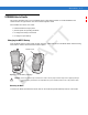
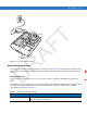
R AF T Chapter 6 Accessories Introduction MC55 accessories, listed below, provide a variety of product support capabilities. • Four Slot Charge Only Cradle - Charges up to four MC55 devices. • Single Slot USB/Serial Cradle - Charges the MC55 main battery and a spare battery. Synchronizes the MC55 with a host computer through a USB or serial connection. • Vehicle Cradle - Provides secure mounting of the MC55 in a vehicle. Charges the MC55 and a spare battery.
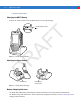
6-2 MC55 User Guide • Charges a spare battery. Charging the MC55 Battery Connect the cradle to power. Insert the MC55 into the slot to begin charging. R AF T Charging/Battery Status LED Figure 6-1 MC55 Battery Charging D Charging the Spare Battery Spare Battery Spare Battery Charging LED Figure 6-2 Spare Battery Charging Battery Charging Indicators The Single Slot USB/Serial Cradle charges the MC55’s main battery and a spare battery simultaneously.
Accessories 6-3 The spare battery charging LED on the cradle indicates the status of the spare battery charging in the cradle. See Table 6-1 for charging status indications. The 2200 mAh battery fully charges in less than five hours and the 3300 mAh battery fully charges in less than seven hours. Charging Temperature Charge batteries in temperatures from 0°C to 40°C (32°F to 104°F). Charging is intelligently controlled by the MC55.
6-4 MC55 User Guide 22003300 Four Slot Charge Only Cradle This section describes how to set up and use a Four Slot Charge Only cradle with the MC55. The Four Slot Charge Only cradle: • Provides 5.4 VDC power for operating the MC55. • Simultaneously charges up to four MC55 devices. R AF Insert the MC55 into a slot to begin charging. T Charging Figure 6-3 MC55 Battery Charging D Battery Charging Indicators The MC55’s charge LED shows the status of the battery charging in the MC55.
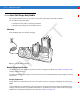
Accessories 6-5 VCD5000 Vehicle Cradle This section describes how to use a VCD5000 vehicle cradle with the MC55. For cradle installation and communication setup procedures refer to the MC55 Integrator Guide. Once installed in a vehicle, the cradle: • holds the MC55 securely in place • provides power for operating the MC55 • re-charges a spare battery. Charging the MC55 Battery T • re-charges the battery in the MC55 R AF Insert the MC55 into the vehicle cradle to begin charging.
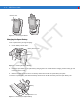
-6 MC55 User Guide T Release Lever Figure 6-5 Removing the MC55 R AF Charging the Spare Battery Insert a spare battery to begin charging: 1. Lift the battery release lever. Battery Release Lever Battery D Figure 6-6 Inserting the Spare Battery 2. Insert the spare battery in the spare battery charging slot in the cradle with the charging contacts facing up and to the rear of the cradle. 3. Release the battery release lever. The battery release lever locks the spare battery into place.
Accessories 6-7 Battery Charging Indicators The Vehicle Cradle charges the MC55’s main battery and a spare battery simultaneously. The MC55’s charge LED indicates the status of the battery charging in the MC55. See Table 1-2 on page 1-8 for charging status indications. The spare battery charging LED on the cradle indicates the status of the spare battery charging in the cradle. See Table 6-2 for charging status indications.
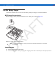
6-8 MC55 User Guide Four Slot Battery Charger This section describes how to use the Four Slot Battery Charger to charge up to four MC55 batteries. MC55 Battery Shim Installation R AF T Before charging a battery, snap the MC55 shim into the battery slot as shown in Figure 6-9. Shim Figure 6-8 MC55 Battery Shim Installation To purchase additional shims, contact your local account manager or Motorola, Inc. Part number: KT-76490-01R. D NOTE Battery Charging 1. Connect the charger to a power source.
Accessories 6-9 R AF T Battery Battery Charging LEDs (4) Figure 6-9 Four Slot Battery Charger Battery Charging Indicators D The charger has an amber LED for each battery charging well. See Table 6-3 for charging status indications. The 2200 mAh battery fully charges in less than five hours and the 3300 mAh battery fully charges in less than seven hours. Charging Temperature Charge batteries in temperatures from 0°C to 40°C (32°F to 104°F). Charging is intelligently controlled by the MC55.
6 - 10 MC55 User Guide Table 6-3 Battery LED Charging Indicators (Continued) LED Indication Battery is charging. Solid Amber Charging complete. Fast Blinking Amber Charging error.
Accessories 6 - 11 Magnetic Stripe Reader (MSR) This section describes how to set up and use the snap-on MSR with the MC55. The MSR snaps on to the bottom of the MC55 and removes easily when not in use. When attached to the MC55, the MSR allows the MC55 to capture data from magnetic stripe cards. To download MSR data capture software, visit the Support Central web site.
Figure 6-11 Magnetic Stripe Card Swiping The application indicates if the data has been read correctly. D R AF 5.
Accessories 6 - 13 Cables This section describes how to set up and use the cables. The cables are available with a variety of connection capabilities. The following communication/charge cables are available: • Serial (RS232) Charge cable (9-pin D female with power input receptacle) • USB Client Charge cable (standard-A connector and a barrel receptacle for power) • DEX cable • Modem inverter cable.
6 - 14 MC55 User Guide 2. Slide the bottom of the MC55 into the connector end of the communication/charge cable and gently press in until it latches into the MC55. The MC55 amber Charge LED indicates the MC55 battery charging status. The 2200 mAh standard battery charges in less than five hours and the 3300 mAh standard battery charges in less than seven hours. See Table 1-2 on page 1-8 for charging status indications. 3.
Accessories 6 - 15 Vehicle Holder WARNING! Some countries prohibit the mounting of any electronic device in any location on the vehicle dashboard. Be sure to check your local laws acceptable mounting areas before installing the auto mounting kit. R AF T Installation Reminders Figure 6-13 Vechile Holder Mounting • Do not mount the vehicle holder where it will obscure the driver’s view of the road. • Do not mount the vehicle holder near the driver seat air bag deployment area.
6 - 16 MC55 User Guide Fix the suction cup mount to the selected area with the suction lever facing up. 2. 3. 4. 5. Flip the lever down to create a vacuum between the suction cup and the mounting surface. Make sure that the suction bond is strong enough before proceeding to the next step. Insert the vehicle holder’s cradle plate to the holes on the back of the cradle. Move the car cradle until both parts are engaged. Slide the MC55 into the cradle. D 6. R AF Figure 6-14 Assembly Vehicle Holder T 1.
D R AF T Accessories 6 - 17
D R AF T 6 - 18 MC55 User Guide
R AF T Chapter 7 Maintenance & Troubleshooting Introduction This chapter includes instructions on cleaning and storing the MC55, and provides troubleshooting solutions for potential problems during MC55 operation. Maintaining the MC55 For trouble-free service, observe the following tips when using the MC55: • Do not scratch the screen of the MC55. When working with the MC55, use the supplied stylus or plastic-tipped pens intended for use with a touch-sensitive screen.
7-2 MC55 User Guide • A screen protector is applied to the MC55. Motorola recommends using this to minimize wear and tear. Screen protectors enhance the usability and durability of touch screen displays. Benefits include: • Protection from scratches and gouges • Durable writing and touch surface with tactile feel • Abrasion and chemical resistance • Glare reduction • Keeping the device’s screen looking new Battery Safety Guidelines T • Quick and easy installation.
Maintenance & Troubleshooting 7-3 Cleaning CAUTION Always wear eye protection. Read warning label on compressed air and alcohol product before using. If you have to use any other solution for medical reasons please contact Motorola for more information. Avoid exposing this product to contact with hot oil or other flammable liquids. If such exposure occurs, unplug the device and clean the product immediately in accordance with these guidelines.
7-4 MC55 User Guide 8. Spray compressed air on the connector area by pointing the tube/nozzle about ½ inch away from the surface. CAUTION: Do not point nozzle at yourself and others, ensure the nozzle or tube is away from your face. 9. Inspect the area for any grease or dirt, repeat if required. Cleaning Cradle Connectors To clean the connectors on a cradle: Remove the DC power cable from the cradle. 2. Dip the cotton portion of the cotton tipped applicator in isopropyl alcohol. 3.
Maintenance & Troubleshooting 7-5 Table 7-1 Troubleshooting the MC55 (Continued) Problem Cause Solution Replace battery. If the MC55 still does not operate, perform a warm boot, then a cold boot. See Resetting the MC55 on page 2-13. MC55 removed from cradle while battery was charging. Insert MC55 in cradle. The 3600 mAh battery fully charges in less than six hours. Extreme battery temperature. Battery does not charge if ambient temperature is below 0°C (32°F) or above 40°C (104°F).
7-6 MC55 User Guide Table 7-1 Troubleshooting the MC55 (Continued) Problem Too many files stored on the MC55. Delete unused memos and records. If necessary, save these records on the host computer (or use an SD card for additional memory). Too many applications installed on the MC55. Remove user-installed applications on the MC55 to recover memory. Select Start > Settings > System tab and tap the Remove Programs icon. Select the unused program and tap Remove. The MC55’s battery is low.
Maintenance & Troubleshooting 7-7 Bluetooth Connection Table 7-2 Troubleshooting Bluetooth Connection Problem Too far from other Bluetooth devices. Move closer to the other Bluetooth device(s), within a range of 10 meters. The Bluetooth device(s) nearby are not turned on. Turn on the Bluetooth device(s) to find. The Bluetooth device(s) are not in discoverable mode. Set the Bluetooth device(s) to discoverable mode. If needed, refer to the device’s user documentation for help.
7-8 MC55 User Guide Table 7-3 Troubleshooting the Single Slot USB/Serial Cradle (Continued) Action MC55 was removed from cradle or cradle was unplugged from AC power too soon. Ensure cradle is receiving power. Ensure MC55 is seated correctly. Confirm main battery is charging under Start > Settings > System > Power. The 3600 mAh battery fully charges in less than six hours. Battery is faulty. Verify that other batteries charge properly. If so, replace the faulty battery.
Maintenance & Troubleshooting 7-9 Vehicle Cradle Table 7-4 Troubleshooting the Vehicle Cradle Symptom Possible Cause Action Cradle is not receiving power. Ensure the power input cable is securely connected to the cradle’s power port. MC55 battery is not recharging. MC55 was removed from the cradle too soon. Replace the MC55 in the cradle. The 3600 mAh battery fully charges in less than six hours. Battery is faulty. Replace the battery. MC55 is not placed correctly in the cradle.
7 - 10 MC55 User Guide Four Slot Battery Charger r Table 7-5 Troubleshooting The Four Slot Battery Charger Action Battery was removed from the charger or charger was unplugged from AC power too soon. Re-insert the battery in the charger or re-connect the charger’s power supply. The 3600 mAh battery fully charges in less than six hours. Battery is faulty. Verify that other batteries charge properly. If so, replace the faulty battery. Battery contacts not connected to charger.
Maintenance & Troubleshooting 7 - 11 Magnetic Stripe Reader Table 7-7 Troubleshooting the Magnetic Stripe Reader MSR cannot read card. Action MSR removed from MC55 during card swipe. Reattach MSR to MC55 and reswipe the card. Faulty magnetic stripe on card. See the system administrator. MSR application is not installed or configured properly. Ensure the MSR application is installed on the MC55. Ensure the MSR application is configured correctly.
D R AF T 7 - 12 MC55 User Guide
R AF T Appendix A Technical Specifications MC55 Technical Specifications The following tables summarize the EDA’s intended operating environment and technical hardware specifications. MC55 EDA Table A-1 MC55 EDA Technical Specifications Item Description Physical Characteristics Length: TBS Width: TBS Depth: TBS Weight (inc. standard battery) TBS D Dimensions Display Transflective color 3.
A-2 MC55 User Guide Table A-1 MC55 EDA Technical Specifications (Continued) Item Description Keypad Options 26 key numeric 44 key QWERTY, 44 key AZERTY, 44 key QWERTZ PIM Audio Speaker, receiver, microphone, headset jack, software support for full duplex record and playback (stereo) Performance Characteristics Intel® XScale™ Bulverde PXA270 processor at 520 MHz Operating System Microsoft® Windows Mobile™ 6 Memory 64 MB RAM/128 MB FLASH 128MB RAM/256MB FLASH R AF T CPU Interface/Communicatio
Using the Interfaces A-3 Table A-1 MC55 EDA Technical Specifications (Continued) Item Description Chan 8-169 (5040 – 5845 MHz) (4920 – 4980 MHz) Japan only Chan 1-13 (2412-2472 MHz) Chan 14 (2484 MHz) Japan only Actual operating frequencies depend on regulatory rules and certification agency Security WPA2, WPA, WEP (40 or 128 bit), TKIP, TLS, TTLS (MS-CHAP), TTLS (MS-CHAP v2), TTLS (CHAP), TTLS-MD5, TTLS-PAP, PEAP-TLS, PEAP (MS-CHAP v2), AES, LEAP Spreading Technique Direct Sequence Spread Spectrum
A-4 MC55 User Guide Table A-1 MC55 EDA Technical Specifications (Continued) Item Description +/- 60° from normal Skew Tolerance +/- 50° from normal Ambient Light Total darkness to 9,000 ft.
Using the Interfaces A-5 Table A-2 Data Capture Options (Continued) Item Code 39 Code 128 Code 93 Codabar Code 11 Interleaved 2 of 5 Discrete 2 of 5 MSI EAN-8 EAN-13 UPCA UPCE UPC/EAN supplementals Coupon Code Trioptic 39 Webcode TLC39 Composite AB Composite C Micro PDF-417 PDF-417 Macro PDF-417 (Macro) Micro PDF-417 QR Code Data Matrix Maxi Code US Postnet* US Planet UK 4-state Australian 4-state Canadian 4-state Japanese 4-state Dutch Kix Chinese 2 of 5 USPS 4-state (US4CB) Aztec microQR GS1 DataBar G
A-6 MC55 User Guide MC55 Accessory Specifications Single Slot USB/Serial Cradle Table A-3 Single Slot USB/Serial Cradle Technical Specifications Feature Description Length: 10.92 cm (4.3 in.) Width: 5.84 cm (2.3 in.) Height: 8.13 cm (3.2 in.) Weight 196 g (6.
Using the Interfaces Table A-4 Four Slot Charge Only Cradle Technical Specifications (Continued) Feature Description Humidity 5% to 95% non-condensing Drop 76.2 cm (30.0 in.) drops to vinyl tiled concrete at room temperature Electrostatic Discharge (ESD) +/- 15 kV air +/- 8 kV contact T Four Slot Battery Charger Table A-5 Four Slot Battery Charger Technical Specifications Feature Length: 20.96 cm (8.25 in.) Width: 15.24 cm (6.0 in.) Height: 4.32 cm (1.7 in.
A-8 MC55 User Guide Table A-6 Magnetic Stripe Reader (MSR) Technical Specifications (Continued) Feature Description 5 to 50 in. (127 to 1270 mm) /sec, bi-directional Decoders Generic, Raw Data Mode Buffered, unbuffered Track Reading Capabilities Tracks 1 and 3: 210 bpi Track 2: 75 and 210 bpi, autodetect Operating Temperature 0°C to 50°C (32°F to 122°F) Storage Temperature -40°C to 70°C (-40°F to 158°F) Humidity 5% to 95% non-condensing Drop 1.22 m (4 ft.
R AF T Appendix A Voice Quality Manager Introduction The Voice Quality Manager (VQM) is a software package that resides on the MC55. VQM enables a set of features for Voice over WiFi (VoWiFi) calls, and a sub-set of those features for cellular line (GSM or CDMA) calls. The VQM user interface is designed to be intuitive and easy to use, so complex tasks such as enabling the Acoustic Echo Canceller (AEC) while a call is in progress are done with very little or no user intervention.
A-2 MC55 User Guide Audio Modes The MC55 can be in any one of the seven different audio modes. The mode is visually indicated by the VQM icon on the title bar. VQM icon Figure A-1 VQM Icon in Title Bar Table A-1 VQM Icons Description R AF Icon T The VQM icon indicates that the device is in speakerphone mode without Acoustic Echo Cancellation (indicated by the gray VQM icon). The audio modes and their corresponding VQM title bar icons are: Speakerphone with Acoustic Echo Cancellation.
Using the Interfaces A-3 The table below lists the current audio mode and the subsequent audio mode after tapping the VQM icon. Table A-2 Changing Audio Modes Audio Mode before Tapping VQM Icon Audio Mode after Tapping VQM Icon Speakerphone Handset Handset Speakerphone Wired headset Wired headset Bluetooth headset Speakerphone T If the audio mode is set to speakerphone and the user taps the VQM icon, the audio mode changes to handset.
A-4 MC55 User Guide Voice Packet Prioritization IP soft phones transmit voice packets in the same manner as any other application that sends data over the network. On a network with different types of traffic, voice packets are given the same priority as any other traffic, and therefore may be subject to delays. WiFi Multi-media (WMM) is a solution to this problem. WMM is a specification that supports prioritizing traffic, and “higher-priority” packets can be given preferential treatment.
A R AF T Glossary API. An interface by means of which one software component communicates with or controls another. Usually used to refer to services provided by one software component to another, usually via software interrupts or function calls Aperture. The opening in an optical system defined by a lens or baffle that establishes the field of view. Application Programming Interface. See API. ANSI Terminal. A display terminal that follows commands in the ANSI standard terminal language.
Glossary - 2 MC55 User Guide Bar Width. Thickness of a bar measured from the edge closest to the symbol start character to the trailing edge of the same bar. BIOS. Basic Input Output System. A collection of ROM-based code with a standard API used to interface with standard PC hardware. Bit. Binary digit. One bit is the basic unit of binary information. Generally, eight consecutive bits compose one byte of data. The pattern of 0 and 1 values within the byte determines its meaning. Bits per Second (bps).
Glossary - 3 Codabar. A discrete self-checking code with a character set consisting of digits 0 to 9 and six additional characters: (“-”, “$”, “:”, “/”, “,” and “+”). Code 128. A high density symbology which allows the controller to encode all 128 ASCII characters without adding extra symbol elements. Code 3 of 9 (Code 39). A versatile and widely used alphanumeric bar code symbology with a set of 43 character types, including all uppercase letters, numerals from 0 to 9 and 7 special characters (“-”, “.
Glossary - 4 MC55 User Guide Device Configuration Package. The Symbol Device Configuration Package provides the Product Reference Guide (PRG), flash partitions, Terminal Configuration Manager (TCM) and the associated TCM scripts. With this package hex images that represent flash partitions can be created and downloaded to the mobile computer. Discrete Code. A bar code or symbol in which the spaces between characters (intercharacter gaps) are not part of the code. Discrete 2 of 5.
Glossary - 5 H Hard Reset. See Cold Boot. Hz. Hertz; A unit of frequency equal to one cycle per second. T Host Computer. A computer that serves other terminals in a network, providing such services as computation, database access, supervisory programs and network control. I IDE. Intelligent drive electronics. Refers to the solid-state hard drive type. R AF IEC. International Electrotechnical Commission.
Glossary - 6 MC55 User Guide IP Address. (Internet Protocol address) The address of a computer attached to an IP network. Every client and server station must have a unique IP address. A 32-bit address used by a computer on a IP network. Client workstations have either a permanent address or one that is dynamically assigned to them each session. IP addresses are written as four sets of numbers separated by periods; for example, 204.171.64.2. IPX/SPX. Internet Package Exchange/Sequential Packet Exchange.
Glossary - 7 MIN are the same value for voice cellular users. International roaming considerations often result in the MDN being different from the MIN. MIL. 1 mil = 1 thousandth of an inch. MIN. Mobile Identification Number. The unique account number associated with a cellular device. It is broadcast by the cellular device when accessing the cellular system. Misread (Misdecode).
Glossary - 8 MC55 User Guide PC Card. A plug-in expansion card for laptop computers and other devices, also called a PCMCIA card. PC Cards are 85.6mm long x 54 mm wide, and have a 68 pin connector. There are several different kinds: Type I; 3.3 mm high; use - RAM or Flash RAM Type II; 5 mm high; use - modems, LAN adaptors Type III; 10.5 high; use - Hard Disks PCMCIA. Personal Computer Memory Card Interface Association. See PC Card. T Percent Decode.
Glossary - 9 RS-232. An Electronic Industries Association (EIA) standard that defines the connector, connector pins, and signals used to transfer data serially from one device to another. S Scan Area. Area intended to contain a symbol. T Scanner. An electronic device used to scan bar code symbols and produce a digitized pattern that corresponds to the bars and spaces of the symbol.
Glossary - 10 MC55 User Guide Symbol. A scannable unit that encodes data within the conventions of a certain symbology, usually including start/stop characters, quiet zones, data characters and check characters. Symbol Aspect Ratio. The ratio of symbol height to symbol width. Symbol Height. The distance between the outside edges of the quiet zones of the first row and the last row. Symbol Length.
Glossary - 11 U UDP. User Datagram Protocol. A protocol within the IP protocol suite that is used in place of TCP when a reliable delivery is not required. For example, UDP is used for real-time audio and video traffic where lost packets are simply ignored, because there is no time to retransmit. If UDP is used and a reliable delivery is required, packet sequence checking and error notification must be written into the applications. T UPC. Universal Product Code. A relatively complex numeric symbology.
D R AF T Glossary - 12 MC55 User Guide
1-D bar codes . . . . . . . . . . . . . . . . . . . . . . . . . . . . . 2-32 2-D bar codes . . . . . . . . . . . . . . . . . . . . . . . . . . . . . 2-32 A vehicle cradle . . . . . . . . . . . . . . . . . . . . 1-4, 6-1, 6-6 wall mounting kit, cradle . . . . . . . . . . . . . . . . . . . 1-5 Zebra printer cable . . . . . . . . . . . . . . . . . . . . . . . 1-4 zebra printer cable . . . . . . . . . . . . . . . . . . . . . . . 1-4 Acoustic Echo Cancellation . . . . . . . . . . . . . . . . . . . .
MC55 User Guide C battery charging . . . . . . . . . . . . . . . . . . . . . . . . . 6-14 LED indicators . . . . . . . . . . . . . . . . . . . . . . . . . . 6-15 conference call . . . . . . . . . . . . . . . . . . . . . . . . . . . . . 5-19 configuration . . . . . . . . . . . . . . . . . . . . . . . . . . . . . 8, 1-5 connectivity icon . . . . . . . . . . . . . . . . . . . . . . . . . . . . . 2-2 contacts application . . . . . . . . . . . . . . . . . . . . . . . . . . 5-5 conventions notational . . . . .
Index - 3 M handset . . . . . . . . . . . . . . . . . . . . . . . . . . . . . . . . . . . A-2 handstrap adjusting . . . . . . . . . . . . . . . . . . . . . . . . . . . . . . 1-10 hard reset . . . . . . . . . . . . . . . . . . . . . . . . . . . . .2-13, 4-4 headset . . . . . . . . . . . . . . . . . . . . 1-4, 5-3, 5-4, 6-1, 6-13 holster . . . . . . . . . . . . . . . . . . . . . . . . . . . . . . . . . . . . 1-4 magnetic stripe reader . . . . . . . . . . . . . . . 1-4, 6-12, 6-13 installation . . . . . . .
MC55 User Guide phone icon . . . . . . . . . . . . . . . . . . . . . . . . . . . . . . . . . 2-2 power button . . . . . . . . . . . . . . . . . . . . . . 1-9, 2-13, 2-30 Q QWERTY keypad input modes . . . . . . . . . . . . . . . . . . 2-21, 2-23, 2-24 QWERTZ . . . . . . . . . . . . . . . . . . . . . . . . . . . . . . . . . 2-18 R S T task tray icons . . . . . . . . . . . . . . . . . . . . . . . . . . . . . . 2-3 technical specifications . . . . . . . . . . . . . . . . . . . . . . . A-1 accessories . .
Index - 5 wireless status . . . . . . . . . . . . . . . . . . . . . . . . . . . . . . 2-3 WLAN 802.11a/b/g . . . . . . . . . . . . . . . . . . . . . . . . . . . . 8 WPAN Bluetooth . . . . . . . . . . . . . . . . . . . . . . . . . . . . . . 8 Z D R AF T Zebra printer cable . . . . . . . . . . . . . . . . . . . . . . . . .
MC55 User Guide D R AF T Index - 6
D T R AF
T R AF D Motorola, Inc. One Motorola Plaza Holtsville, New York 11742, USA 1-800-927-9626 http://www.motorola.com MOTOROLA and the Stylized M Logo and Symbol and the Symbol logo are registered in the U.S. Patent and Trademark Office. All other product or service names are the property of their registered owners. © Motorola, Inc.