Accessories Chapter Contents Introduction . . . . . . . . . . . . . . . . . . . . . . . . . . . . . . . . . . . . . . . . . . . . . . . . . . . . . . . . . . . . . . . . . . . . . . . . . . . . . 4-3 Cradles . . . . . . . . . . . . . . . . . . . . . . . . . . . . . . . . . . . . . . . . . . . . . . . . . . . . . . . . . . . . . . . . . . . . . . . . . . . . . 4-3 Spare Battery Chargers . . . . . . . . . . . . . . . . . . . . . . . . . . . . . . . . . . . . . . . . . . . . . . . . . . . . . . . . . . . . . .
4-2 MC3000 User Guide Plastic Holster. . . . . . . . . . . . . . . . . . . . . . . . . . . . . . . . . . . . . . . . . . . . . . . . . . . . . . . . . . . . . . . . . . . . . . . . . . .4-14 Fabric Holster . . . . . . . . . . . . . . . . . . . . . . . . . . . . . . . . . . . . . . . . . . . . . . . . . . . . . . . . . . . . . . . . . . . . . . . . . . .4-16 Belt Clip . . . . . . . . . . . . . . . . . . . . . . . . . . . . . . . . . . . . . . . . . . . . . . . . . . . . . . . . . . . . . . . . . . . . . .
Accessories 4-3 Introduction The MC3000 accessories provide a variety of product support capabilities. Accessories include cradles, cables, spare battery chargers and SD cards. Cradles • • • The Single Slot Serial/USB cradle charges the mobile computer main battery and/or a spare battery. It also synchronizes the mobile computer with a host computer through either a serial or a USB connection. The Four Slot Charge Only cradle charges up to four mobile computers.
-4 MC3000 User Guide Single Slot Serial/USB Cradle The Single Slot Serial/USB cradle: • • • • • Provides 5.4VDC power for operating the mobile computer, charging the battery and charging a spare battery. Provides a serial port and a USB port for data communication between the mobile computer and a host computer or other serial devices (e.g., a printer). Synchronizes information between the mobile computer and a host computer.
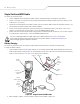
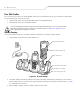
Accessories 4-5 To charge the spare battery: 1. Insert the spare battery into the spare battery charging slot, bottom first, and pivot the top of the battery down onto the contact pins. 2. Gently press down on the battery to ensure proper contact. 3. The Spare Battery Charging LED (see Figure 4-1 on page 4-4) indicates the spare battery charging status. The Standard Battery charges in less than four hours and the Extended Life Battery charges in less than six hours.
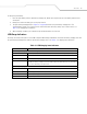
4-6 MC3000 User Guide Four Slot Cradles There are two four slot cradles, Four Slot Charge Only cradle and Four Slot Ethernet cradle. The Four Slot Ethernet cradle provides Ethernet communications. Both four slot cradles: • • Provide 5.4 VDC power for operating the mobile computer and charging the battery. Simultaneously charges up to four mobile computers. Use only a Symbol approved power supply output rated 12 VDC and minimum 9 A.
Accessories 4-7 LED Charge Indications The Four Slot cradles use the mobile computer amber Charge LED Indicator to indicate the battery charging status. See Table 4-1 on page 4-5 for charging status indications. Power LED The green Power LED (only on the Four Slot Charge Only cradle) lights to indicate that the Four Slot Charge Only cradle is connected to a power source. Speed LED The green Speed LED (only on the Four Slot Ethernet cradle) lights to indicate that the transfer rate is 100 Mbps.
4-8 MC3000 User Guide Four Slot Spare Battery Charger The Four Slot Spare Battery Charger simultaneously charges up to four spare batteries. Use only a Symbol approved power supply output rated 12 VDC and minimum 3.3 A. Use of an alternative power supply will void the product warranty and may cause product damage. See Appendix C, Regulatory for the power supply regulatory compliance statement. Spare Battery Charging To charge up to four MC3000 spare batteries: 1.
Accessories 4-9 Cables The cables are available with a variety of connection capabilities. Use only a Symbol approved power supply output rated 5.4 VDC and minimum 3 A. Use of an alternative power supply will void the product warranty and may cause product damage. See Appendix C, Regulatory for the power supply regulatory compliance statement. MC3000 Communication/Charge cables: • • • • Provide the mobile computer with operating and charging power when used with the Symbol approved power supply.
4-10 MC3000 User Guide Battery Charging and Operating Power The MC3000 Communication/Charge cables can charge the mobile computer battery and supply operating power. To charge the mobile computer battery: 1. Connect the MC3000 Communication/Charge cable power input connector to the Symbol approved power source. 2. Slide the bottom of the mobile computer into the MC3000 connector end of the MC3000 Communication/Charge cable and gently press in until the snaps latch into the mobile computer. 3.
Accessories 4-11 Universal Battery Charger (UBC) Adapter The UBC Adapter can be used with a power supply as a standalone spare battery charger or it can be used with the four station UBC2000 to simultaneously charge up to four spare batteries. For additional information on the UBC 2000, refer to the UBC 2000 Quick Reference Guide p/n 70-33188-xx. Use only a Symbol approved power supply output rated 15 VDC and minimum 1.5 A.
4-12 MC3000 User Guide UBC Adapter LED Charge Indications The UBC Adapter charging LEDs indicate the battery charging status. The Standard Battery usually charges in less than four hours and the Extended Life Battery usually charges in less than six hours. POWER READY or STANDBY or FAULT (Green) (Flashing Yellow) (Solid Yellow) CHARGING (Solid Yellow) Figure 4-6. UBC Adapter LEDs Table 4-2.
Accessories 4-13 Secure Device Card The Secure Device (SD) card provides secondary non-volatile storage (the flash memory is slower than RAM). The SD card holder is located under the battery. Follow proper Electro-Static Discharge (ESD) precautions to avoid damaging the SD card. Proper ESD precautions include, but are not limited to, working on an ESD mat and ensuring that the operator is properly grounded. Do not use the SD card slot for any other accessories.
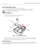
4-14 MC3000 User Guide Plastic Holster The Plastic Holster provides a holder for the mobile computer. It consists of a mobile computer holder and a detachable belt clip. Press the release button to remove the detachable belt clip. Release Button Detachable Belt Clip Mobile Computer Holder Figure 4-8. Plastic Holster Pinch the clip release and attach the Plastic Holster to a belt or waist band. Clip Release Mobile Computer Holder Figure 4-9.
Accessories 4-15 To insert the mobile computer, slide the mobile computer into the Plastic Holster with the screen facing the user. To remove the mobile computer, press and lift to remove the mobile computer. Insert Mobile Computer Remove Mobile Computer Figure 4-10.
4-16 MC3000 User Guide Fabric Holster The Fabric Holster provides a soft holder for the mobile computer. It consists of a fabric mobile computer holder, a detachable shoulder strap and a detachable belt clip. Press the release button to remove the detachable belt clip. See Figure 4-11 to remove the detachable clip see Figure 4-12 on page 4-16 to attach the Fabric Holster to a belt and see Figure 4-13 on page 4-17 to attach the Fabric Holster to a shoulder strap.
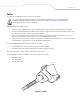
Accessories 4-17 Shoulder Strap Remove the detachable belt clip (see Figure 4-11 on page 4-16) and attach the shoulder strap. Shoulder Strap Clip Release Figure 4-13. Attach the Fabric Holster To the Shoulder Strap The Fabric Holster holds the mobile computer on a belt or waist band. 1. 2. 3. 4. To insert the mobile computer, slide the mobile computer into the Fabric Holster with the screen facing the user. Pull restraining strap over mobile computer and secure in the clip.
4-18 MC3000 User Guide
Maintenance & Troubleshooting Introduction . . . . . . . . . . . . . . . . . . . . . . . . . . . . . . . . . . . . . . . . . . . . . . . . . . . . . . . . . . . . . . . . . . . . . . . . . . . . 5- 3 Maintaining the Mobile Computer. . . . . . . . . . . . . . . . . . . . . . . . . . . . . . . . . . . . . . . . . . . . . . . . . . . . . . . . . . . . 5-3 Troubleshooting . . . . . . . . . . . . . . . . . . . . . . . . . . . . . . . . . . . . . . . . . . . . . . . . . . . . . . . . . . . . . . . . . . . . . . .
5-2 MC3000 User Guide
Maintenance & Troubleshooting 5-3 Introduction This chapter includes instructions on cleaning and storing the mobile computer, and provides troubleshooting solutions for potential problems during mobile computer operation. Maintaining the Mobile Computer For trouble-free service, observe the following tips when using the mobile computer: • • • • • • Do not scratch the screen of the mobile computer.
5-4 MC3000 User Guide Troubleshooting Mobile Computer Table 5-1. Troubleshooting the Mobile Computer Problem Mobile computer does not turn on. Battery did not charge. Cause Solution Main battery not charged. Charge or replace the main battery. Main battery not installed properly. Ensure the battery is installed properly. See Install Main Battery on page 1-6. System crash. Perform a warm boot. If the mobile computer still does not turn on, perform a cold boot.
Maintenance & Troubleshooting 5-5 Table 5-1. Troubleshooting the Mobile Computer (Continued) Problem The mobile computer does not accept scan input. Cause Solution Scanning application is not loaded. Verify that the mobile computer is loaded with a scanning application. See the system administrator. Unreadable bar code. Ensure the symbol is not defaced. Distance between scan window and bar code is incorrect. Ensure the mobile computer is within proper scanning range.
5-6 MC3000 User Guide Single Slot Serial/USB Cradle Table 5-2. Troubleshooting the Single Slot Serial/USB Cradle Symptom Possible Cause Solution Mobile computer amber Charge Cradle is not receiving power. LED Indicator does not light when mobile computer inserted. Mobile computer is not correctly seated. Ensure the power cable is connected securely to both the cradle and to AC power. Spare Battery Charging LED does not light when spare battery is inserted. Spare battery is not correctly seated.
Maintenance & Troubleshooting 5-7 Four Slot Charge Only Cradle Table 5-3. Troubleshooting the Four Slot Charge Only Cradle Problem Cause Solution Mobile computer amber Charge LED Indicator does not light when mobile computer inserted. Cradle is not receiving power. Ensure the power cable is connected securely to both the cradle and to AC power. Mobile computer is not correctly seated. Remove and re-insert the mobile computer into the cradle, ensuring it is correctly seated.
5-8 MC3000 User Guide Four Slot Spare Battery Charger Table 5-5. Troubleshooting the Four Slot Spare Battery Charger Symptom Possible Cause Solution Spare Battery Charging LED does not light when spare battery is inserted. Spare battery is not correctly seated. Remove and re-insert the spare battery into the charging slot, ensuring it is correctly seated. Spare battery is not charging. Charger is not receiving power. Ensure the power cable is connected securely to both the charger and to AC power.
Maintenance & Troubleshooting 5-9 Cables Table 5-7. Troubleshooting the Cables Symptom Possible Cause Mobile computer amber Charge Cable is not receiving power. LED Indicator does not light Mobile computer is not seated when mobile computer correctly in the cable. attached. Solution Ensure the power cable is connected securely to both the cable and to AC power. Remove and re-attach the mobile computer to the MC3000 connector, ensuring it is correctly seated.
5-10 MC3000 User Guide
Technical Specifications Appendix Contents Mobile Computer And Accessory Technical Specifications . . . . . . . . . . . . . . . . . . . . . . . . . . . . . . . . . . . . . . .
A-2 MC3000 Integrator Guide
Technical Specifications A-3 Mobile Computer And Accessory Technical Specifications Table A-1 summarizes the mobile computer technical specifications and intended operating environments. Table A-2 summarizes the accessory technical specifications and the intended operating environments. Table A-1.
A-4 MC3000 Integrator Guide Table A-1. Mobile Computer Technical Specifications (Continued) Processor/Memory Intel® XScale™ PXA270 312MHz with 32MB RAM/64MB Flash or Intel® XScale™ PXA270 520MHz with 64MB RAM/64MB Flash Interface RS232, 115.2 kbps max, and USB WLAN Symbol Spectrum 24, 802.
Keypad Functions/Special Characters Appendix Contents Introduction . . . . . . . . . . . . . . . . . . . . . . . . . . . . . . . . . . . . . . . . . . . . . . . . . . . . . . . . . . . . . . . . . . . . . . . . . . . . .B-3 Keypads . . . . . . . . . . . . . . . . . . . . . . . . . . . . . . . . . . . . . . . . . . . . . . . . . . . . . . . . . . . . . . . . . . . . . . . . . . . . . . . .
B-2 MC3000 User Guide
Keypad Functions/Special Characters B-3 Introduction This appendix contains the keypad functions/special characters for the 38-Key keypad. Each function/special character is included in the table along with how the function/special character is generated. Keypads The mobile computer is available with one of three keypads: • • • 28-key keypad 38-key keypad 48-key keypad. The keypads can be selected as necessary to support specialized applications.
B-4 MC3000 User Guide Table B-1. Special Character Generation Map Special Character 28-Key Keypad Key Sequence, Special Character Generation 38-Key Keypad Key Sequence, Special 48-Key Keypad Key Sequence, Special Character Generation Character Generation [ Use the Keyboard Input Panel* FUNC + 4 FUNC + T ] Use the Keyboard Input Panel* FUNC + 5 FUNC + U / Use the Keyboard Input Panel* FUNC + 9 FUNC + Q \ Use the Keyboard Input Panel* FUNC + 3 Use the Keyboard Input Panel* = Use the Keyb
Regulatory Appendix Contents Introduction . . . . . . . . . . . . . . . . . . . . . . . . . . . . . . . . . . . . . . . . . . . . . . . . . . . . . . . . . . . . . . . . . . . . . . . . . . . . .B-3 Accessory Power Supply Regulatory Compliance . . . . . . . . . . . . . . . . . . . . . . . . . . . . . . . . . . . . . . . . . . . . . . . .
C-2 MC3000 User Guide
Regulatory C-3 Introduction This appendix contains the accessory power supply regulatory compliance statements. Accessory Power Supply Regulatory Compliance Table C-1. Accessory Power Supplies, Regulatory Compliance Statements Accessory Power Supplies Regulatory Compliance Statements Single Slot Serial/USB Cradle Power Supply Use only a Symbol-approved power supply output rated 12 VDC and minimum 3.3 A. The power supply is certified to EN60950 with SELV outputs.
C-4 MC3000 User Guide
Glossary 802.11/802.11abg A radio protocol that may be used by the Symbol radio card. Access Point Access Point (AP) refers to Symbol’s Ethernet Access Point. It is a piece of communications equipment that manages communications between the host computer system and one or more wireless terminals. An AP connects to a wired Ethernet LAN and acts as a bridge between the Ethernet wired network and IEEE 802.11 interoperable radioequipped mobile units, such as a mobile computer.
GL-2 MC3000 User Guide AirBEAM® Smart Client AirBEAM® Smart Client is part of Symbol’s AirBEAM® suite, which also includes AirBEAM® Safe and AirBEAM® Manager. The AirBEAM® Smart Client system uses the network accessible host server to store software files that are to be downloaded to the mobile computers. The AirBEAM® Smart Client provides the mobile computers with the “smarts” to request software from the host.
Glossary GL-3 Byte On an addressable boundary, eight adjacent binary digits (0 and 1) combined in a pattern to represent a specific character or numeric value. Bits are numbered from the right, 0 through 7, with bit 0 the low-order bit. One byte in memory is used to store one ASCII character. boot or boot-up The process a computer goes through when it starts. During boot-up, the computer can run self-diagnostic tests and configure hardware and software. CDRH Center for Devices and Radiological Health.
GL-4 MC3000 User Guide COM port Communication port; ports are identified by number, e.g., COM1, COM2. Continuous Code A bar code or symbol in which all spaces within the symbol are parts of characters. There are no intercharacter gaps in a continuous code. The absence of gaps allows for greater information density. Cradle A cradle is used for charging the terminal battery and for communicating with a host computer, and provides a storage place for the terminal when not in use.
Glossary GL-5 Flash Memory Flash memory is responsible for storing the system firmware and is non-volatile. If the system power is interrupted the data is not be lost. Gateway Address An IP address for a network gateway or router. A mobile computer may be part of a subnet as specified by its IP address and Netmask. It can send packets directly to any node on the same subnet. If the destination node is on a different subnet, then the terminal sends the packet to the gateway first.
GL-6 MC3000 User Guide Interleaved 2 of 5 A binary bar code symbology representing character pairs in groups of five bars and five interleaved spaces. Interleaving provides for greater information density. The location of wide elements (bar/spaces) within each group determines which characters are encoded. This continuous code type uses no intercharacter spaces. Only numeric (0 to 9) and START/STOP characters may be encoded. Internet Protocol Address See IP. IP Internet Protocol.
Glossary GL-7 Mobile Computer In this text, mobile computer refers to the Symbol portable computer. It can be set up to run as a stand-alone device, or it can be set up to communicate with a network, using wireless radio technology. Nominal The exact (or ideal) intended value for a specified parameter. Tolerances are specified as positive and negative deviations from this value. Nominal Size Standard size for a bar code symbol. Most UPC/EAN codes are used over a range of magnifications (e.g., from 0.
GL-8 MC3000 User Guide Scanning Mode The scanner is energized, programmed and ready to read a bar code. Scanning Sequence A method of programming or configuring parameters for a bar code reading system by scanning bar code menus. SDK Software Development Kit Self-Checking Code A symbology that uses a checking algorithm to detect encoding errors within the characters of a bar code symbol. Shared Key Shared Key authentication is an algorithm where both the AP and the MU share an authentication key.
Glossary GL-9 Symbol Length Length of symbol measured from the beginning of the quiet zone (margin) adjacent to the start character to the end of the quiet zone (margin) adjacent to a stop character. Symbology The structural rules and conventions for representing data within a particular bar code type (e.g. UPC/EAN, Code 39, PDF417, etc.). Tolerance Allowable deviation from the nominal bar or space width. UPC Universal Product Code. A relatively complex numeric symbology.
GL-10 MC3000 User Guide
Index Numerics 28-key keypad . . . . . . . . . . . . . . . . . . . . . . . . . . 2-4, B-3 38-key keypad . . . . . . . . . . . . . . . . . . . . . . . . . . 2-6, B-3 48-key keypad . . . . . . . . . . . . . . . . . . . . . . . . . . 2-8, B-3 802.11 . . . . . . . . . . . . . . . . . . . . . . . . . . . . . . . . . . . A-4 A accessories . . . . . . . . . . . . . . . . . . . . . . . . . . . . . . . .1-3 cables . . . . . . . . . . . . . . . . . . . . . . . . . . . . . . . .4-9 four slot charge only cradle . . .
IN-2 MC3000 User Guide main battery . . . . . . . . . . . . . . . . . . . . . . . . . . .1-9 MC3000 communication/charge cables . . . . .4-10 battery charging . . . . . . . . . . . . . . . . . . .4-10 temperature range . . . . . . . . . . . . . . . . . . . . . .1-9 UBC adapter . . . . . . . . . . . . . . . . . . . . . . . . . .4-11 battery status . . . . . . . . . . . . . . . . . . . . . . . . . . . . . .2-11 beeper . . . . . . . . . . . . . . . . . . . . . . . . . . . . . . . . . . . .1-4 beeper volume .
Index IN-3 I N icons navigating software . . . . . . . . . . . . . . . . . . . . . . . . . .2-3 bluetooth . . . . . . . . . . . . . . . . . . . . . . . 2-11, 2-12 Imager image capture . . . . . . . . . . . . . . . . . . . . . . . . 2-19 imager . . . . . . . . . . . . . . . . . . . . . . . . . . . . . . . . . . . 2-19 aiming . . . . . . . . . . . . . . . . . . . . . . . . . . . . . . 2-19 decode mode . . . . . . . . . . . . . . . . . . . . . . . . . 2-19 function . . . . . . . . . . . . . . . . . . . .
IN-4 MC3000 User Guide range . . . . . . . . . . . . . . . . . . . . . . . . . . . . . . . .2-17 scanning considerations . . . . . . . . . . . . . . . . . . . . .2-17 screen calibration . . . . . . . . . . . . . . . . . . . . . . . . . . . .1-11 contrast . . . . . . . . . . . . . . . . . . . . . . . . . . . . . . .2-3 specifications . . . . . . . . . . . . . . . . . . . . . . . . . A-3 SD card . . . . . . . . . . . . . . . . . . . . . . . . . . . . . . . . . . .4-13 installation . . . . . . . . . . . . .
Tell Us What You Think... We’d like to know what you think about this Manual. Please take a moment to fill out this questionnaire and fax this form to: (631) 738-3318, or mail to: Symbol Technologies, Inc. One Symbol Plaza M/S B-4 Holtsville, NY 11742-1300 Attention: Technical Publications Manager IMPORTANT: If you need product support, please call the appropriate customer support number provided. Unfortunately, we cannot provide customer support at the fax number above.
Symbol Technologies, Inc. One Symbol Plaza Holtsville, New York 11742-1300 http://www.symbol.