
User's Manual


Technical Specifications A - 5
MC18 Interface Connector Pin-Outs
Figure A-1
Power Connector Pin-Outs
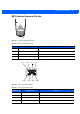
Figure A-2
Sync Connector Pin-Outs
Table A-4
Power Connector Pin-Outs
PIN Signal Name Function
1 GND Ground
2 TX Transmit Output to Cradle
3 RX Receive Input from Cradle
4 +5V Input power.
Table A-5
Sync Connector Pin-Outs
PIN Number Signal Name Function
1USB_PWR +5 VDC
2 USBA0_OTG_DP USB DATA +
3 Reserved Not Used
4 USBA0_OTG_DM USB DATA -
Pin 1
Pin 1 Pin 5 Pin 7Pin 3
Pin 2 Pin 6 Pin 8Pin 4