
User Manual


XXXXXXXX Rev X
LA-5137 CF card Integration Guide
Copyright 2004 Symbol Technologies, Inc. Page 13 of 17
Confidential Material – Disclosure Strictly Prohibited.
Note: This equipment has been tested and found to comply with the limits for a
Class B digital device, pursuant to Part 15 of the FCC rules. These limits are
designed to provide reasonable protection against harmful interference in a
residential installation. This equipment generates, uses and can radiate radio
frequency energy and, if not installed and used in accordance with the
instructions, may cause harmful interference to radio communications. However
there is no guarantee that interference will not occur in a particular installation. If
this equipment does cause harmful interference to radio or television reception,
which can be determined by turning the equipment off and on, the user is
encouraged to try to correct the interference by one or more of the following
measures:
• Reorient or relocate the receiving antenna
• Increase the separation between the equipment and receiver
• Connect the equipment into an outlet on a circuit different from that to which
the receiver is connected
• Consult the dealer or an experienced radio/TV technician for help.
Radio Transmitters (Part 15)
This device complies with Part 15 of the FCC Rules. Operation is subject to the
following two conditions: (1) this device may not cause harmful interference, and
(2) this device must accept any interference received, including interference that
may cause undesired operation.
2.4GHz band operation
The available channels for 802.11 b/g operation in the US are Channels 1 to 11.
The range of channels is limited by firmware.
UNII band 1
The use in the UNII (Unlicensed National Information Infractructure) band 1 5150-
5250 MHz band is restricted to Indoor Use Only; any other use will make the
operation of this device illegal.
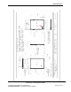
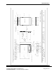
4. Appendix 1: Product Mechanical Interface Drawing
The following drawings show the Product physical size and shape, LED indicator
and connector locations and pin assignments. Red arrow shows the primary
antenna connector.