
User's Manual

XXXXXXXX Rev X
LA-5127 CF card Integration Guide
Copyright 2004 Symbol Technologies, Inc. Page 9 of 37
Confidential Material – Disclosure Strictly Prohibited.
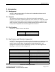
11 2462 USA, Canada, EU, Japan
12 2467 EU, Japan
13 2472 EU, Japan
14 2484 Japan
Table 1. IEEE 802.11g Channels
2.2.8 Electrical Interface
The electrical interface for LA-5127 is PC16. The chipset used supports this
interface; therefore no external component is required. The host must support the
PC16 interface as well. The card uses only the 16-bit interface.
2.2.9 Bluetooth Coexistence and Wake-on-WLAN
LA-5127 hardware is being designed to support these features for future software
implementation. AT THIS TIME THESE FEATURES ARE NOT SUPPORTED BY
THE SOFTWARE.
Three GPIO pins have been assigned to support the BT Coexistence. The
following is the assignment to support the BT Coexistence with Broadcom’s
BCM2045 BT module:
GPIO 2-3: BT0 (Tx Config) (Connected to pin A10 on CF interface)
GPIO 2-4: BT1 (Status) (Connected to pin CSEL on CF interface)
GPIO 2-5: BT2 (RF Active) (Connected to pin SPKR on CF interface)
The following GPIO signal is also available for Wake-on-WLAN functionality:
GPIO 2-11: WOL (Connected to STSCHG on CF interface)
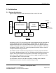
3. Design Overview
The chipset used implements a dual band direct conversion transceiver
supporting 2.4GHz band. The chipset uses “Zero Intermediate Frequency (ZIF)
architecture for the radio. The architecture contains low-noise amplifiers, quad
up/down converters, frequency synthesizers, low-pass filters, baseband AGC
receiver amplifiers, transmit/receive switches, and transmitter power amplifiers.