
User's Manual

XXXXXXXX Rev X
LA-5127 CF card Integration Guide
Copyright 2004 Symbol Technologies, Inc. Page 6 of 37
Confidential Material – Disclosure Strictly Prohibited.
2. Architecture
2.1 System Architecture
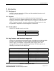
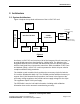
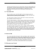
Figure 1 depicts the top-level architecture of the LA-5127 CF card.
Figure 1
As shown, LA-5127 CF card consists of all of the integrated circuits necessary to
provide WLAN transceiver functionality for 2.4GHz band. The Wireless LAN
integrated Media Access Controller with Baseband processor directly interfaces
with the Dual Band Direct Conversion transceiver. With the addition of RF Front-
end Module (FEM), LA-5127 CF card incorporates the WLAN chip set solution
compliant with 802.11b/g standards.
The 40MHz crystal controlled clock provides the necessary clocks for both the
PLL and the baseband & MAC chip. The SDRAM provides additional memory to
support SHoC (Self Hosted Client) operation. Not shown in the figure are the
necessary voltage regulators that provide various supply voltages for the chips.
The regulators require 3.3V input supply.
The EEPROM is used to hold radio information including radio calibration
information done at the automatic manufacturing test step.
2.4GHz
Transceiver
CF Host I/F
RF
FEM
Baseband & MAC
40Mhz
Clock
EEPROM
SDRAM
32.768Khz
Clock
To Antenna
(Antenna Version)
To RF Connectors
(
Connector Version
)