
User's Manual

12 EMG101 Gateway
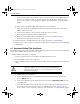
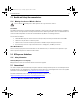
For power adapter (Part Number PWRS-147376-01R) and line cord installations:
a. Connect a RJ-45 CAT5e (or CAT6) Ethernet cable between the network data supply (host) and the
Gateway’s GE1/PoE.
b. Verify the power adapter is correctly rated according the country of operation.
c. Connect the power supply line cord to the power adapter.
d. Attach the power adapter cable to the DC-48V power connector on the Gateway.
e. Attach the power supply line cord to a power supply.
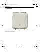
4. Verify the behavior of the Gateway LED. For more information, see
Basic Gateway Configuration.
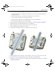
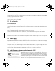
5. Align the bottom of the ceiling T-bar with the back of the Gateway.
6. Orient the Gateway chassis by its length and the length of the ceiling T-bar.
7. Rotate the Gateway chassis 45 degrees clockwise.
8. Push the back of the Gateway chassis on to the bottom of the ceiling T-bar.
9. Rotate the Gateway chassis 45 degrees counter-clockwise. The clips click as they fasten to the T-bar.
10. Verify the behavior of the Gateway LED. For more information, see
LED Indicator.
11. The Gateway is ready to configure. For information on basic Gateway device configuration, see
Basic
Gateway Configuration
.
MN000995A01.fm Page 12 Tuesday, August 26, 2014 2:27 PM