coverBook Page i Monday, December 1, 1997 2:19 PM LS 1000 Product Reference Guide Click on red text at any location in the manual to jump to the specified chapter, topic, or reference.
coverBook Page iii Monday, December 1, 1997 2:19 PM Copyright 1996 by Symbol Technologies, Inc. All rights reserved. No part of this publication may be reproduced or used in any form, or by any electrical or mechanical means, without permission in writing from Symbol. This includes electronic or mechanical means, such as photocopying, recording, or information storage and retrieval systems. The material in this manual is subject to change without notice.
coverBook Page iv Monday, December 1, 1997 2:19 PM Factory Service If you have a problem, contact the Symbol Support Center at the telephone number on the next page. Before calling, have the model number and several of your bar code symbols at hand. Call the Support Center from a phone near the scanning equipment so that the service person can try to talk you through your problem.
coverBook Page v Monday, December 1, 1997 2:19 PM Symbol Support Center In the U.S.A., for service information, warranty information or technical assistance call: SYMBOL SUPPORT CENTER 1-800-653-5350 If you purchased your Symbol product from a Symbol Business Partner, contact that Business Partner for service.
coverBook Page vii Monday, December 1, 1997 2:19 PM Contents Factory Service Symbol Support Center Chapter 1. Introduction and Set-up Introduction Audience Set-Up3 Unpacking Installing the Cable Switching Cables Connecting to a Host Chapter 2. Scanning Introduction Ready, Test, Scan Aiming Chapter 3. Maintenance & Specifications Introduction Maintaining the LS 1000 Scanner Accessories LS 100x Technical Specifications LS 100x Decode Zone Chapter 4.
coverBook Page viii Monday, December 1, 1997 2:19 PM PPT 4600 Product Reference Guide: Contents Decode Attempt Time Operating Mode Aggressive Scan Mode Transmit “No Decode” Message Decode Redundancy Code Types UPC/EAN Code 128 Code 39 Code 93 Interleaved 2 of 5 Discrete 2 of 5 Codabar Data Options RS-232C Chapter 5. Glossary Chapter 6. ASCII Character Set ASCII Character Set Appendix A.
coverBook Page 1 Monday, December 1, 1997 2:19 PM Chapter 1 Introduction and Set-up Introduction Symbol Technologies Inc., the world leader in hand-held laser scanning now offers 21st century technology, while maintaining compatibility with today’s existing systems. The LS 1000 Series of hand-held laser scanners offers the best performance in retail and light industrial applications. Advanced ergonomic design ensures comfortable use for extended periods of time.
coverBook Page 2 Monday, December 1, 1997 2:19 PM LS 1000 Product Reference Guide: Chapter 1, Introduction and Setup Audience The intended audience for this manual is personnel performing installation/setup and programming of LS 100x scanners.
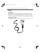
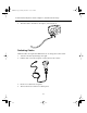
coverBook Page 3 Monday, December 1, 1997 2:19 PM LS 1000 Product Reference Guide: Chapter 1, Introduction and Setup Set-Up Unpacking Remove the scanner from its packing and inspect it for damage. If the scanner was damaged in transit, call the Symbol Support Center at one of the telephone numbers listed in the front of this manual. KEEP THE PACKING. It is the approved shipping container and should be used if you ever need to return your equipment for servicing. Installing the Cable 1.
coverBook Page 4 Monday, December 1, 1997 2:19 PM LS 1000 Product Reference Guide: Chapter 1, Introduction and Setup 2. Twist the cable to the left to lock in place, as shown below: Switching Cables Different cables are required for different hosts. To change the scanner cable: 1. “Unlock” the cable by twisting to the right. 2. Pull the cable out of the receptacle on the bottom of the scanner. 3. Insert a new cable in the receptacle. 4. Twist to the left to lock the new cable in place.
coverBook Page 5 Monday, December 1, 1997 2:19 PM LS 1000 Product Reference Guide: Chapter 1, Introduction and Setup Connecting to a Host With some terminal types, the LS 100x is unable to answer host terminal polls until the appropriate host type is selected. This may result in an error message generated by the host. To correct this situation, select proper parameter values and initialize the host terminal. See Chapter 4 for more information.
coverBook Page 6 Monday, December 1, 1997 2:19 PM LS 1000 Product Reference Guide: Chapter 1, Introduction and Setup For external power operation with Flying Lead Connector • Plug the cable into the scanner. • Plug the Power Supply into the receptacle on the Flying Lead connector. Figure 1-2.
coverBook Page 7 Monday, December 1, 1997 2:19 PM LS 1000 Product Reference Guide: Chapter 1, Introduction and Setup For external power operation with 25-pin Host Connector • Plug the cable into the scanner. • Plug the Power Supply into the receptacle on the side of the 25-pin Host Connector Figure 1-3.
coverBook Page 8 Monday, December 1, 1997 2:19 PM LS 1000 Product Reference Guide: Chapter 1, Introduction and Setup RS-232C (Contd) For battery operation: • Insert a 9-volt battery into the battery box. See Battery Box Operation . • Plug the scanner's 9-pin connector at the end of the cord into one end of the battery box. • An output cable from the battery box connects the LS 1000 to the RS-232C input device.
coverBook Page 9 Monday, December 1, 1997 2:19 PM LS 1000 Product Reference Guide: Chapter 1, Introduction and Setup IBM 468X/9X Plug the SDL modular connector at the end of the selected Synapse “Smart” cable into the appropriate port (5B, 9B, 9C, 9E, or 17). Check that the connection is secure. To install an LS 1004 on an IBM 468X/469X host: 1. Connect a synapse adaptor cable to the scanner, using the procedure described in “Installing the Cable ” . 2.
coverBook Page 10 Monday, December 1, 1997 2:19 PM LS 1000 Product Reference Guide: Chapter 1, Introduction and Setup IBM 468X/9X (Contd) PORT 5B PORT 9B PORT 17 Figure 1-6. IBM 4683 Rear Panel with Cover Removed 9B 5B 17 Figure 1-7.
coverBook Page 11 Monday, December 1, 1997 2:19 PM LS 1000 Product Reference Guide: Chapter 1, Introduction and Setup IBM 468X/9X (Contd) 5B 9C 9B Figure 1-8. IBM 4693 Rear Panel with Cover Removed PORT 9E IBM 4694 REAR PANEL WITH COVER REMOVED Figure 1-9. IBM 4694 Rear Panel with Cover Removed Wand Emulation, OCIA, OCR, and Keyboard Wedges A Synapse Adaptor Cable is required when connecting the LS 1004 to any of these hosts using Synapse.
coverBook Page 1 Monday, December 1, 1997 2:19 PM Chapter 2 Scanning Introduction This chapter covers the techniques involved in scanning bar codes. Included are specific instructions on how to hold the scanner at the appropriate angle to ensure an accurate decode.
coverBook Page 2 Monday, December 1, 1997 2:19 PM LS 1000 Product Reference Guide: Chapter 2, Scanning Ready, Test, Scan 1. Ready Make sure all connections are secure. 2. Test Aim the scanner away from you and press the trigger. When you press the trigger, the scanning beam is energized. On the LS 1000, the length of time the beam remains on depends on the controller or terminal into which it is plugged. On the LS 1004, the scanner is energized for approximately 1 second (default). 3.
coverBook Page 3 Monday, December 1, 1997 2:19 PM LS 1000 Product Reference Guide: Chapter 2, Scanning Aiming Scan the Entire Symbol • Your scan beam must cross every bar and space on the symbol. • The larger the symbol, the farther away you should hold the scanner. • Hold the scanner closer for symbols with bars that are close together. • A short, high tone beep indicates a good decode.
coverBook Page 4 Monday, December 1, 1997 2:19 PM LS 1000 Product Reference Guide: Chapter 2, Scanning Hold at an Angle Do not hold the scanner directly over the bar code. Laser light reflecting directly back into the scanner from the bar code is known as specular reflection. This strong light can “blind” the scanner and make decoding difficult. The area where specular reflection occurs is known as a “dead zone”. You can tilt the scanner up to 65° forward or back and achieve a successful decode.
coverBook Page 1 Monday, December 1, 1997 2:19 PM Chapter 3 Maintenance & Specifications Introduction This chapter covers the suggested maintenance of the LS 100x scanner, as well as the technical specifications, available accessories, pinouts, and beeper definitions.
coverBook Page 2 Monday, December 1, 1997 2:19 PM LS 1000 Product Reference Guide: Chapter 3, Maintenance and Specifications Maintaining the LS 1000 Scanner Battery Box Operation When using the LS 1000 Series with a battery box, you can use either an alkaline battery (recommended), or a nickel-cadmium rechargeable battery. Low power is signalled by 4 short, high-tone beeps, coupled with scanning interruptions. If this occurs, change or recharge the battery as soon as possible.
coverBook Page 3 Monday, December 1, 1997 2:19 PM LS 1000 Product Reference Guide: Chapter 3, Maintenance and Specifications Maintenance Cleaning the exit window is the only maintenance required. • Do not allow any abrasive material to touch the window. • Remove any dirt particles with a damp cloth. • Wipe the window using a damp cloth, and if necessary, a non-ammonia based detergent. • Do not spray water or other cleaning liquids directly into the window.
coverBook Page 4 Monday, December 1, 1997 2:19 PM LS 1000 Product Reference Guide: Chapter 3, Maintenance and Specifications Accessories Required Accessories Required accessories are listed in the Product Ordering Guide. Optional accessories are available at extra cost. Table 3-1. LS 1000 Required Accessories Part Number Description ND1221 One undecoded cable 70-17422-01 LS 1000 Series Quick Reference Guide Table 3-1.
coverBook Page 5 Monday, December 1, 1997 2:19 PM LS 1000 Product Reference Guide: Chapter 3, Maintenance and Specifications What If... Nothing happens when you follow the operating instructions? You Should • Check the system power; is there a battery in the battery box? • Be sure the scanner is programmed for the terminal in use. • Make sure the scanner is programmed to read the type of bar code you are scanning. • Check for loose cable connections. • Check the symbol to make sure it is not defaced.
coverBook Page 6 Monday, December 1, 1997 2:19 PM LS 1000 Product Reference Guide: Chapter 3, Maintenance and Specifications LS 100x Technical Specifications LS 100x Decode Zone In. Cm. 10 25.4 5 12.7 0 0 5 12.7 Scanner 5.0 mil 1.0 2.3 10 25.4 7.5 mil 5.0 0 13 mil 2.0 In. 0 Cm. 0 9.0 20 mil minimum element width 5 12.7 10 25.4 15.0 15 38.1 Depth of Field in Inches/Centimeters Depth of field as a function of minimum element width. Figure 3-1.
coverBook Page 7 Monday, December 1, 1997 2:19 PM LS 1000 Product Reference Guide: Chapter 3, Maintenance and Specifications Table 3-1. Technical Specifications (LS 1000) Item Power Requirements* Discrete Description 4.8 to 14 VDC (max) 80 mA @ 5VDC typical Decode Capability Transmission of decoded information will depend on the capabilities of the attached terminal.
coverBook Page 8 Monday, December 1, 1997 2:19 PM LS 1000 Product Reference Guide: Chapter 3, Maintenance and Specifications Table 3-1. Technical Specifications (LS 1000) (Continued) Item Description Operating Temperature 32° to 104°F0° to 40°C Storage Temperature -40° to 140°F-40° to 60°C Humidity 5% to 95% (non-condensing) Durability 4-ft. drop to concrete1.2 m Dimensions Height Length Width 4.8 in.122 mm 3.7 in.93 mm 2.4 in.
coverBook Page 9 Monday, December 1, 1997 2:19 PM LS 1000 Product Reference Guide: Chapter 3, Maintenance and Specifications Table 3-2. Technical Specifications (LS 1004) Item Power Requirements* RS-232C/Synapse Low Power Description 4.75 to 14.5 VDC (max) 100mA @ 5VDC typical 4.
coverBook Page 10 Monday, December 1, 1997 2:19 PM LS 1000 Product Reference Guide: Chapter 3, Maintenance and Specifications Table 3-2. Technical Specifications (LS 1004) (Continued) Item Description Operating Temperature 32° to 104°F0° to 40°C Storage Temperature -40° to 140°F-40° to 60°C Humidity 5% to 95% (non-condensing) Durability 4-ft. drop to concrete1.2 m Dimensions Height Length Width 4.8 in.122 mm 3.7 in.93 mm 2.4 in.
coverBook Page 11 Monday, December 1, 1997 2:19 PM LS 1000 Product Reference Guide: Chapter 3, Maintenance and Specifications Table 3-3. Pinouts - LS 1000 Pin LS 1000 Function 1 VBAT Power Supply 2 VBAT Power Supply 3 GND Ground 4 ENABLE Scan Enable 5 SOS Start of Scan 6 TRIGGER* Trigger Signal 7 DECODE Successful Decode 8 DBP Digital Bar Pattern 9 N.C. Non-Connected 10 N.C.
coverBook Page 12 Monday, December 1, 1997 2:19 PM LS 1000 Product Reference Guide: Chapter 3, Maintenance and Specifications Table 3-4. Pinouts - LS 1004 Pin LS 1004 Function 1 Data Data Line (for synapse) 2 VBAT Power Supply 3 GND Ground 4 RTS Request to Send (for RS-232C) 5 RXD* Receive Data Input (for RS-232C) 6 N.C.
coverBook Page 13 Monday, December 1, 1997 2:19 PM LS 1000 Product Reference Guide: Chapter 3, Maintenance and Specifications Table 3-5. Beeper Indications Standard Use Beeper Sequence Indication 1 Beep - short high tone A bar code symbol was decoded (if decode beeper is enabled). 4 Beeps - long low tone A transmission error has been detected in a scanned symbol. The last data scanned was lost. Scan the last data again.
coverBook Page 1 Monday, December 1, 1997 2:19 PM Chapter 4 Programming The LS 1004 Introduction This chapter provides information on how to program the LS 1004 scanner. Before programming the scanner, follow the instructions in the Appendix section of Chapter 1. The default table, shown on the following page, illustrates the default values with which the scanner is shipped. If the default values suit your requirements, scan the Appendix barcode. This will set the scanner to the default parameters.
coverBook Page 2 Monday, December 1, 1997 2:19 PM LS 1000 Product Reference Guide: Chapter 4, Programming the LS 1004 The following table lists the defaults for all parameters. If you wish to change any option, scan the appropriate bar code(s) Table 4-1.
coverBook Page 3 Monday, December 1, 1997 2:19 PM LS 1000 Product Reference Guide: Chapter 4, Programming the LS 1004 Table 4-1.
coverBook Page 4 Monday, December 1, 1997 2:19 PM LS 1000 Product Reference Guide: Chapter 4, Programming the LS 1004 Table 4-1.
coverBook Page 5 Monday, December 1, 1997 2:19 PM LS 1000 Product Reference Guide: Chapter 4, Programming the LS 1004 Scanning Sequence A scanning sequence establishes a value for one parameter type. During a scanning sequence, bar codes are scanned to select a parameter. All bar codes necessary for programming the scanner are provided in the Appendix section of this manual.
coverBook Page 6 Monday, December 1, 1997 2:19 PM LS 1000 Product Reference Guide: Chapter 4, Programming the LS 1004 Parameter Descriptions Refer to the Default table in the front of this chapter for the default settings for each parameter type. Set Parameter Defaults Scanning the SET ALL DEFAULTS bar code returns all parameters to the default values listed in the Default Table. SET ALL DEFAULTS Host Interface Select Scan the bar code corresponding to your host type.
coverBook Page 7 Monday, December 1, 1997 2:19 PM LS 1000 Product Reference Guide: Chapter 4, Programming the LS 1004 Power On Beep Enable/Disable This option, if selected, causes the beeper to sound at power-up (in continuous power mode only). Power On Beep Disable Power On Beep Enable Beeper after Decode This option determines whether the beeper sounds during normal scanning. Usually, it is desirable to operate the unit with the beeper enabled.
coverBook Page 8 Monday, December 1, 1997 2:19 PM LS 1000 Product Reference Guide: Chapter 4, Programming the LS 1004 Beeper Volume Three options are available for beeper volume; low, middle, and high.
coverBook Page 9 Monday, December 1, 1997 2:19 PM LS 1000 Product Reference Guide: Chapter 4, Programming the LS 1004 Decode Attempt Time This parameter sets the length of time the scanner laser beam will remain on while attempting to scan a symbol. 0.5 seconds 3.5 seconds 1.0 seconds 4.0 seconds 1.5 seconds 4.5 seconds 5.0 seconds 2.0 seconds 2.5 seconds 5.5 seconds 3.0 seconds 6.
coverBook Page 10 Monday, December 1, 1997 2:19 PM LS 1000 Product Reference Guide: Chapter 4, Programming the LS 1004 Decode Attempt Time (cont’d) 7.0 seconds 6.5 seconds Operating Mode This parameter determines whether or not power remains on after a decode attempt. The LOW POWER option provides for power-down after each scan attempt, while the CONTINUOUS option provides for power to remain on after each scan attempt.
coverBook Page 11 Monday, December 1, 1997 2:19 PM LS 1000 Product Reference Guide: Chapter 4, Programming the LS 1004 Transmit “No Decode” Message This feature gives you the option to transmit “NR” when a symbol does not decode. Prefixes and suffixes enabled will be appended around this character.
coverBook Page 12 Monday, December 1, 1997 2:19 PM LS 1000 Product Reference Guide: Chapter 4, Programming the LS 1004 Code Types Selecting the ENABLE ALL CODE TYPES bar code below enables the following symbologies: • UPC Versions A and E (EAN 8 and 13) • Code 39 • Interleaved 2 of 5 • Code 93 • Codabar • Discrete 2 of 5 • Code 128 • Code 39 Full ASCII The scanner autodiscriminates between all of the above symbologies, except for Code 39 and Code 39 Full ASCII.
coverBook Page 13 Monday, December 1, 1997 2:19 PM LS 1000 Product Reference Guide: Chapter 4, Programming the LS 1004 UPC/EAN Enable/Disable UPC/EAN Disable UPC/EAN Enable UPC/EAN Transmit UPC-E/UPC-A Select this option if decoded UPC-E or UPC-A symbols are transmitted with or without the check digit.
coverBook Page 14 Monday, December 1, 1997 2:19 PM LS 1000 Product Reference Guide: Chapter 4, Programming the LS 1004 Convert UPC-E to UPC-A Select this option to convert UPC-E (zero suppressed) decode data to UPC-A format before transmission. After conversion, data follows UPC-A format and is affected by UPC-A programming selections (e.g., Preamble, Check Digit).
coverBook Page 15 Monday, December 1, 1997 2:19 PM LS 1000 Product Reference Guide: Chapter 4, Programming the LS 1004 Decode UPC/EAN Supplemental This option is used to select whether UPC/EAN is decoded with or without supplemental characters, or whether the unit will autodiscriminate between the two. Supplementals are additionally appended characters, according to specific code format conventions (e.g., UPC A+2, UPC E+2, EAN 8+5).
coverBook Page 16 Monday, December 1, 1997 2:19 PM LS 1000 Product Reference Guide: Chapter 4, Programming the LS 1004 UPC A and E Preamble(s) Three options are available for the lead-in characters for decoded UPC-A or UPC-E symbols transmitted to the host device. Select one preamble for UPC-A decodes and one for UPC-E decodes. These lead-in characters are considered part of the symbol itself.
coverBook Page 17 Monday, December 1, 1997 2:19 PM LS 1000 Product Reference Guide: Chapter 4, Programming the LS 1004 UPC/EAN Security Level The scanner offset four levels of decode security for UPC/EAN bar codes. Increasing levels of security are provided for decreasing levels of bar code quality. There is an inverse relationship between security and scanner aggressiveness, so be sure to choose only that level of security necessary for any given application.
coverBook Page 18 Monday, December 1, 1997 2:19 PM LS 1000 Product Reference Guide: Chapter 4, Programming the LS 1004 Code 128 Enable/Disable Code 128 Disable CODE 128 Enable CODE 128 Send CODE 128 Function Character If selected, CODE 128 function characters are sent as: • FN1=0X1D • FN2=0X81 • FN3=0X82 • FN4=0X83 This option will be enabled when data format is 8 bits.
coverBook Page 19 Monday, December 1, 1997 2:19 PM LS 1000 Product Reference Guide: Chapter 4, Programming the LS 1004 Code 39 Enable/Disable Code 39 Enable Code 39 Disable Code 39 CODE 39 Modulo 43 Check When enabled, this parameter checks the integrity of a CODE 39 symbol to ensure it complies with specified algorithms. Verify Code 39 Check Digit Do Not Verify Code 39 Check Digit Transmit CODE 39 Check Digit When enabled, CODE 39 Check Digit will be sent to the host.
coverBook Page 20 Monday, December 1, 1997 2:19 PM LS 1000 Product Reference Guide: Chapter 4, Programming the LS 1004 Code 93 Enable/Disable Code 93 Enable Code 93 Disable Code 93 4-20
coverBook Page 21 Monday, December 1, 1997 2:19 PM LS 1000 Product Reference Guide: Chapter 4, Programming the LS 1004 Interleaved 2 of 5 Enable/Disable Code I 2 of 5 Enable Code I 2 of 5 Disable Code I 2 of 5 Fixed Lengths for Code I 2 of 5 Select one or two lengths for the Interleaved 2 of 5 codes. If you set both Length 1 and Length 2 to 0, the scanner can read any length within 36 characters.
coverBook Page 22 Monday, December 1, 1997 2:19 PM LS 1000 Product Reference Guide: Chapter 4, Programming the LS 1004 Fixed Lengths for Code 2 of 5 (cont’d) 0 1 2 3 4 5 7 6 9 8 CANCEL 4-22
coverBook Page 23 Monday, December 1, 1997 2:19 PM LS 1000 Product Reference Guide: Chapter 4, Programming the LS 1004 I 2 of 5 Modulo 10 Check When enabled, this parameter checks the integrity of a Interleaved 2 of 5 symbol to ensure it complies with specific algorithms. I 2of 5 Modulo 10 Check Digit Enable I 2of 5 Modulo 10 Check Digit Disable ITF14/EAN13 Conversion This feature converts a 14-character I 2 of 5 code into EAN13, and transmits to the host as EAN13.
coverBook Page 24 Monday, December 1, 1997 2:19 PM LS 1000 Product Reference Guide: Chapter 4, Programming the LS 1004 Discrete 2 of 5 Enable/Disable D 2 of 5 Enable Code D 2 of Disable Code D 2 of D 2 of 5 Modulo 10 Check When enabled, this parameter checks the integrity of a Discrete 2 of 5 symbol to ensure it complies with specific algorithms.
coverBook Page 25 Monday, December 1, 1997 2:19 PM LS 1000 Product Reference Guide: Chapter 4, Programming the LS 1004 Fixed Lengths for Code 2 of 5 (cont’d) 0 1 2 3 4 5 7 6 9 8 CANCEL 4-25
coverBook Page 26 Monday, December 1, 1997 2:19 PM LS 1000 Product Reference Guide: Chapter 4, Programming the LS 1004 Codabar Enable/Disable Codabar Enable Codabar Disable Codabar CLSI Editing Use this parameter to insert a space after the 1st, 5th, and 10th characters of a 14character Codabar symbol. This symbol length includes start and stop characters. Enable CLSI Editing Disable CLSI Editing NOTIS Editing This option strips the start and stop characters from decoded Codabar symbols.
coverBook Page 27 Monday, December 1, 1997 2:19 PM LS 1000 Product Reference Guide: Chapter 4, Programming the LS 1004 Data Options Transmit Code ID Character A code ID character identifies the code type of a scanned bar code. This may be useful when the scanner is decoding more than one code type. In addition to any singlecharacter prefixes already selected, the code ID character is appended as a prefix to the decode.
coverBook Page 28 Monday, December 1, 1997 2:19 PM LS 1000 Product Reference Guide: Chapter 4, Programming the LS 1004 Prefix The scanner adds one of the following start-of-text characters to transmitted data. • None • Start-of-text (STX) • One user-defined prefix (can be any ASCII character) See the ASCII Character Table in Appendix A for more information.
coverBook Page 29 Monday, December 1, 1997 2:19 PM LS 1000 Product Reference Guide: Chapter 4, Programming the LS 1004 Suffix • Select one or two end-of-text characters to be added to transmitted data. • None • CR (Carriage Return) - Returns the cursor to the same position on the line after each decode. • LF (Line Feed) - Moves the cursor down a line after each decode. • CR & LF - Allow you to select where the cursor on a display terminal returns to after it displays each decoded symbol.
coverBook Page 30 Monday, December 1, 1997 2:19 PM LS 1000 Product Reference Guide: Chapter 4, Programming the LS 1004 Prefix/Suffix Values 0 1 2 3 4 5 6 7 9 8 CANCEL 4-30
coverBook Page 31 Monday, December 1, 1997 2:19 PM LS 1000 Product Reference Guide: Chapter 4, Programming the LS 1004 RS-232C Baud Rate Baud Rate is the number of bits of data transmitted per second. The unit’s baud rate setting should match the data rate setting of the host device. If not, data may not reach the host device, or may reach it in distorted form.
coverBook Page 32 Monday, December 1, 1997 2:19 PM LS 1000 Product Reference Guide: Chapter 4, Programming the LS 1004 Parity A parity check bit is the most significant bit of each ASCII coded character. If you select ODD parity, the parity bit will have a value of 0 or 1, based on data, to ensure that an odd number of 1 bits are contained in the coded character.
coverBook Page 33 Monday, December 1, 1997 2:19 PM LS 1000 Product Reference Guide: Chapter 4, Programming the LS 1004 Data Format This parameter sets the transmit data format. The options are: • 7 Data Bits (With Parity) (default) • 8 Data Bits (With Parity) • 8 Data Bits (Without Parity) 8-Bit 7-Bit Stop Bit Select The stop bit(s) at the end of each transmitted character marks the end of transmission of one character and prepares the receiving device for the next character in the serial data stream.
coverBook Page 34 Monday, December 1, 1997 2:19 PM LS 1000 Product Reference Guide: Chapter 4, Programming the LS 1004 Hardware Handshaking Hardware handshaking allows you to check the readiness of the receiving device before data is transmitted. If the receiving device is periodically occupied with other tasks, hardware handshaking is needed to prevent loss of transmitted data.
coverBook Page 35 Monday, December 1, 1997 2:19 PM LS 1000 Product Reference Guide: Chapter 4, Programming the LS 1004 Software Handshaking This parameter offers control of the data transmission process in addition to, or instead of, that offered by hardware handshaking. These options may be combined; for example, ACK/NAK with ENQ. • No software handshaking None • ACK/NAK only The ACK/NAK option checks the success or failure of transmission.
coverBook Page 36 Monday, December 1, 1997 2:19 PM LS 1000 Product Reference Guide: Chapter 4, Programming the LS 1004 transmission error occurs. ENQ Only • ACK/NAK with ENQ This option combines both handshaking options.
coverBook Page 37 Monday, December 1, 1997 2:19 PM LS 1000 Product Reference Guide: Chapter 4, Programming the LS 1004 Hardware and Software Handshaking Sequence HARDWARE HANDSHAKING SYMBOL IS DECODED RTS AND CTS HANDSHAKING LINES USED YES NO NO REPONSE. AFTER 2 SECONDS, THE UNIT BEEPS 4 TIMES TO INDICATE A TRANSMISSION ERROR. UNIT ASSERTS REQUEST-TO-SEND LINE. HOST RESPONDS BY ASSERTING CLEAR-TO-SEND LINE. SOFTWARE HANDSHAKING ENQ SWITCH ON? NO YES NO REPONSE.
coverBook Page 38 Monday, December 1, 1997 2:19 PM LS 1000 Product Reference Guide: Chapter 4, Programming the LS 1004 Communications Delays and Time-Outs (Intercharacter Delay) Selecting the intercharacter delay gives the host system time to service its receiver and perform other tasks between characters. Select from no delay to a 99 msec. delay between transmission of each character.
coverBook Page 39 Monday, December 1, 1997 2:19 PM LS 1000 Product Reference Guide: Chapter 4, Programming the LS 1004 Intercharacter Delay Values (cont’d) 0 1 2 3 4 5 7 6 9 8 CANCEL 4-39
coverBook Page 1 Monday, December 1, 1997 2:19 PM Chapter 5 Glossary ASCII - American Standard Code for Information Interchange. A 7 bit code representing 128 letters, numerals, punctuation marks, and control characters. It is a standard data transmission code in the U.S. BIT - Binary digit. One bit is the basic unit of binary information. Generally, eight consecutive bits compose one byte of data. The pattern of 0 and 1 values within the byte determines its meaning.
coverBook Page 2 Monday, December 1, 1997 2:19 PM LS 1000 Series Product Reference Guide CODE 3 OF 9 (CODE 39) - A versatile and widely used alphanumeric bar code symbology with a set of 43 character types, including all uppercase letters, numerals from 0 to 9, and 7 special characters (- . / + % $ and space). The code name is derived from the fact that 3 of 9 elements representing a character are wide, while the remaining 6 are narrow.
coverBook Page 3 Monday, December 1, 1997 2:19 PM Glossary IEC CLASS I (IEC 825 Class I) - This is the lowest power IEC laser classification. Conformity is ensured through a software restriction of 25 seconds of laser operation within any 100 second window and an automatic laser shutdown if the scanner's oscillating mirror fails. INTERCHARACTER GAP - The space between two adjacent bar code characters in a discrete bar code.
coverBook Page 4 Monday, December 1, 1997 2:19 PM LS 1000 Series Product Reference Guide SCANNER - An electronic device used to scan bar code symbols and produce a digitized pattern that corresponds to the bars and spaces of the symbol. Its three main components are: 1. Light source (laser or photoelectric cell) - illuminates a bar code. 2. Photodetector - registers the difference in reflected light (more light reflected from spaces). 3.
coverBook Page 1 Monday, December 1, 1997 2:19 PM Chapter 6 ASCII Character Set ASCII Character Set Table 6-1. ASCII Character Set ASCII Value Full ASCII Code 39 Encode Char.
coverBook Page 2 Monday, December 1, 1997 2:19 PM PPT 4600 Product Reference Guide: Getting Started Table 6-1. (Continued) ASCII Character Set 021 $U CTRL U 045 - - 022 $V CTRL V 046 . . 023 $W CTRL W 047 / / ASCII Value Full ASCII Code 39 Encode Char.
coverBook Page 3 Monday, December 1, 1997 2:19 PM PPT 4600 Product Reference Guide: Getting Started Table 6-1. (Continued) ASCII Character Set 072 H H 097 +A a ASCII Value Full ASCII Code 39 Encode Char.
coverBook Page 1 Monday, December 1, 1997 2:19 PM Appendix A Errata Table A-1. ASCII Character Set 264 ALT 2 275 ALT K 286 ALT V 265 ALT A 276 ALT L 287 ALT W 266 ALT B 277 ALT M 288 ALT X 267 ALT C 278 ALT N 289 ALT Y 268 ALT D 279 ALT O 290 ALT Z 269 ALT E 280 ALT P 291 ALT [ 270 ALT F 281 ALT Q 292 ALT \ 271 ALT G 282 ALT R 293 ALT ] 272 ALT H 283 ALT S 294 ALT 6 273 ALT I 284 ALT T 295 ALT - 274 ALT J 285 ALT U Misc. Key Keystroke Misc.
coverBook Page 2 Monday, December 1, 1997 2:19 PM LS 1000 Product Reference Guide: Appendix A, Errata Shee PF Keys Keystroke PF Keys Keystroke PF Keys Keystroke 401 PF 1 409 PF 9 417 PF 17 402 PF 2 410 PF 10 418 PF 18 403 PF 3 411 PF 11 419 PF 19 404 PF 4 412 PF 12 420 PF 20 405 PF 5 413 PF 13 421 PF 21 406 PF 6 414 PF 14 422 PF 22 407 PF 7 415 PF 15 423 PF 23 408 PF 8 416 PF 16 424 PF 24 F Keys Keystroke F Keys Keystroke F Keys Keystroke 501 F1
coverBook Page 3 Monday, December 1, 1997 2:19 PM LS 1000 Product Reference Guide: Appendix A, Errata Sheet Numeric Keypad Keystroke Numeric Keypad Keystroke Numeric Keypad Keystroke 642 * 649 1 656 8 643 + 650 2 657 9 644 Undefined 651 3 658 Enter 645 - 662 4 659 Num Lock 646 .
coverBook Page 4 Monday, December 1, 1997 2:19 PM LS 1000 Product Reference Guide: Appendix A, Errata Shee 70-19761-01 Rev.
coverBook Page 1 Monday, December 1, 1997 2:19 PM Tell Us What You Think... We’d like to know what you think about this Manual. Please take a moment to fill out this questionaire and fax this form to: (516) 738-3318, or mail to: Symbol Technologies, Inc. One Symbol Plaza M/S B-4 Holtsville, NY 11742-1300 Attn: Technical Publications Manager IMPORTANT: If you need product support, please call the appropriate customer support number provided.