
User's Manual


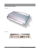
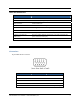
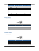
Table Of Contents
- Contents
- Section 1. Introduction
- Section 2. System Description
- Section 3. Specifications and Diagrams
- Section 4. Installing the Reader
- Section 5. Configuring the Reader
- Section 6. Notification of Events
- Section 7. Tag Selection Filters
- Section 8. Reader Server Controls
- Section 9. Ad-hoc Queries
- Section 10. Maintaining the Reader
- Access the Reader Maintenance Console
- Manage Communication Configuration Settings
- Manage System Time Settings
- Display Version Control Information and Load Firmware via FTP
- Display the System Log and/or Access History
- Shut Down and/or Restart the System, and Turn Off the HTTP Server
- Use Online Help
- Log Out of the System
- Section 11. Cautions, Notes, and Approvals
- Section 12. Warranties and Returns
- Section 13. Contact Us
- Appendix A. Error Messages and Resolutions

AR 400 Reader User’s Manual 2003-2004 Matrics, Inc. 5
LEDs and Connectors
ITEM DESCRIPTION
RJ45 Connector 10BaseT Ethernet
DB9 Connector RS232 Console (Management)
DB15 Connector Control I/O Port (6)
RS422/RS485 Connector Connect to host PC and bus power.
Power/Link LED LED is green when the Reader is powered on and linked to the host PC.
Error LED LED is red when commands are incorrectly received from the host PC.
Read LED LED is yellow when commands are correctly received from the host PC.
+24vDC 1.2A Connector
(Unit Power)
The power supply should be plugged into a wall outlet and into the DC
power connector (2.1mm jack.)
Mini-UHF Antenna Connectors Connect to external antennas (4 Transmit and 4 Receive.)
Interface Pin-Outs
I/O Interface
15-pin Female D-sub Connector:
PIN: FUNCTION PIN: FUNCTION PIN: FUNCTION
1: Ground 6: In2 11: Out1
2: Out4 7: In0 12: In5
3: Out2 8: Ground 13: In3
4: Out0 9: Out5 14: In1
5: In4 10: Out3 15: Vcc +5V power supply