
User Manual Part 3
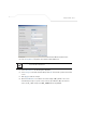
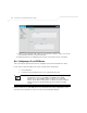
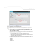
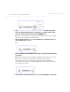
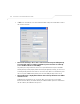
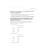


Table Of Contents
- Introduction
- 1.1 New Features
- 1.2 Feature Overview
- 1.2.1 Single or Dual Mode Radio Options
- 1.2.2 Separate LAN and WAN Ports
- 1.2.3 Multiple Mounting Options
- 1.2.4 Antenna Support for 2.4 GHz and 5.2 GHz Radios
- 1.2.5 Sixteen Configurable WLANs
- 1.2.6 Support for 4 BSSIDs per Radio
- 1.2.7 Quality of Service (QoS) Support
- 1.2.8 Industry Leading Data Security
- 1.2.9 VLAN Support
- 1.2.10 Multiple Management Accessibility Options
- 1.2.11 Updatable Firmware
- 1.2.12 Programmable SNMP v1/v2/v3 Trap Support
- 1.2.13 Power-over-Ethernet Support
- 1.2.14 MU-MU Transmission Disallow
- 1.2.15 Voice Prioritization
- 1.2.16 Support for CAM and PSP MUs
- 1.2.17 Statistical Displays
- 1.2.18 Transmit Power Control
- 1.2.19 Advanced Event Logging Capability
- 1.2.20 Configuration File Import/Export Functionality
- 1.2.21 Default Configuration Restoration
- 1.2.22 DHCP Support
- 1.2.23 Multi-Function LEDs
- 1.3 Theory of Operations
- Hardware Installation
- Getting Started
- System Configuration
- Network Management
- Configuring Access Point Security
- 6.1 Configuring Security Options
- 6.2 Setting Passwords
- 6.3 Enabling Authentication and Encryption Schemes
- 6.4 Configuring Kerberos Authentication
- 6.5 Configuring 802.1x EAP Authentication
- 6.6 Configuring WEP Encryption
- 6.7 Configuring KeyGuard Encryption
- 6.8 Configuring WPA Using TKIP
- 6.9 Configuring WPA2-CCMP (802.11i)
- 6.10 Configuring Firewall Settings
- 6.11 Configuring VPN Tunnels
- 6.12 Configuring Content Filtering Settings
- 6.13 Configuring Rogue AP Detection
- 6.14 Configuring User Authentication
- Monitoring Statistics
- Command Line Interface Reference
- Configuring Mesh Networking
- Technical Specifications
- Usage Scenarios
- Customer Support
- Index
AP-51xx Access Point Product Reference Guide
B-12
19. On access point #2/ Device #2, repeat the same procedure. However, replace access point
#2 information with access point #1 information.
20. Once both tunnels are established, ping each side of the tunnel to ensure connectivity.
B.2.2 Configuring a Cisco VPN Device
This section includes general instructions for configuring a Cisco PIX Firewall 506 series device.
For the usage scenario described in this section, you will require the following:
• 1 Cisco VPN device
• 1 PC connected to the LAN side of the access pointand the Cisco PIX.
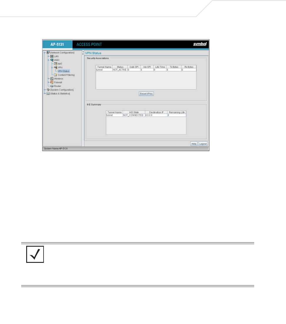
Below is how the access point VPN Status screen should look if the entire configuration is setup
correctly once the VPN tunnel is active. The status field should display "ACTIVE".
NOTE The Cisco PIX device configuration should match the access point VPN
configuration in terms of Local WAN IP (PIX WAN), Remote WAN
Gateway (access point WAN IP), Remote Subnet (access point LAN
Subnet), and the Remote Subnet Mask. The Auto Key Settings and the IKE
Settings on the Cisco PIX should match the access point Key and IKE
settings.