
User Manual Part 3
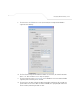
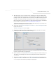
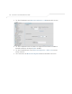
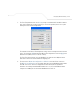
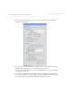
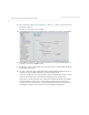
Table Of Contents
- Introduction
- 1.1 New Features
- 1.2 Feature Overview
- 1.2.1 Single or Dual Mode Radio Options
- 1.2.2 Separate LAN and WAN Ports
- 1.2.3 Multiple Mounting Options
- 1.2.4 Antenna Support for 2.4 GHz and 5.2 GHz Radios
- 1.2.5 Sixteen Configurable WLANs
- 1.2.6 Support for 4 BSSIDs per Radio
- 1.2.7 Quality of Service (QoS) Support
- 1.2.8 Industry Leading Data Security
- 1.2.9 VLAN Support
- 1.2.10 Multiple Management Accessibility Options
- 1.2.11 Updatable Firmware
- 1.2.12 Programmable SNMP v1/v2/v3 Trap Support
- 1.2.13 Power-over-Ethernet Support
- 1.2.14 MU-MU Transmission Disallow
- 1.2.15 Voice Prioritization
- 1.2.16 Support for CAM and PSP MUs
- 1.2.17 Statistical Displays
- 1.2.18 Transmit Power Control
- 1.2.19 Advanced Event Logging Capability
- 1.2.20 Configuration File Import/Export Functionality
- 1.2.21 Default Configuration Restoration
- 1.2.22 DHCP Support
- 1.2.23 Multi-Function LEDs
- 1.3 Theory of Operations
- Hardware Installation
- Getting Started
- System Configuration
- Network Management
- Configuring Access Point Security
- 6.1 Configuring Security Options
- 6.2 Setting Passwords
- 6.3 Enabling Authentication and Encryption Schemes
- 6.4 Configuring Kerberos Authentication
- 6.5 Configuring 802.1x EAP Authentication
- 6.6 Configuring WEP Encryption
- 6.7 Configuring KeyGuard Encryption
- 6.8 Configuring WPA Using TKIP
- 6.9 Configuring WPA2-CCMP (802.11i)
- 6.10 Configuring Firewall Settings
- 6.11 Configuring VPN Tunnels
- 6.12 Configuring Content Filtering Settings
- 6.13 Configuring Rogue AP Detection
- 6.14 Configuring User Authentication
- Monitoring Statistics
- Command Line Interface Reference
- Configuring Mesh Networking
- Technical Specifications
- Usage Scenarios
- Customer Support
- Index

Configuring Mesh Networking
9-41
13. The team still does not want any MUs connecting to the mesh WLAN, only the devices
comprising the mesh network. Therefore, the team leaves the Maximum MUs field as is,
and will use the Radio Configuration page to control the number of client bridge connections
within the mesh WLAN.
14. The team verifies the Enable Client Bridge Backhaul checkbox is selected for both AP5
and AP6 to ensure the WLAN is available in the WLAN drop-down menu within the Radio
Configuration screen.
15. The IT team then verifies that steps 10 through 14 have been carried out identically for both
AP5 and AP6.
The IT team now needs to define a security policy for AP5 and AP4 complimentary with the
policy created for APs 1-4.
16. The IT Team defines a WPA2/CCMP security policy exactly like the one created for APs 1-4.
For more information, see how the team initially defined the security policy starting on step
16 within Trion’s Initial Deployment on page 9-19.
17. Existing MU traffic within the mesh network will be used within the expanded shipping yard.
Thus, the IT team refers to the ACLs created for APs 1-4 and defines an ACL exactly like it
for AP5 and AP6. The team also remembers to go to the ACL for AP1, AP3 and AP4 and add
AP5 and AP6 in order for each device in the mesh network to communicate with one another.
For more information, refer to step 22 within Trion’s Initial Deployment on page 9-19.
18. The team decides to leave the Disallow MU to MU Communication checkbox unselected
for AP5 and AP6, as the team still considers all MU traffic within the shipping yard known
and not a threat to the growing mesh network.
19. The team selects the Use Secure Beacon checkbox from the Edit WLAN screen to not
transmit the AP- 5131’s ESSID between APs 1 through 6. If a hacker tries to find an ESSID
via an MU, the AP- 5131’s ESSID does not display since the ESSID is not in the beacon.
20. The team does not select the Accept Broadcast ESSID checkbox, as they still do not want
MUs randomly joining their carefully constructed mesh network.
21. The IT Team still envisions little (if any) video or voice traffic within the shipping as the MUs
within primarily scan bar codes and upload data. This still holds true for the QoS
requirements for AP5 and AP6, as the required coverage area has continued to grow, but not
the security, access permissions or QoS considerations. For more information, see how the
team defined the QoS policy for APs 1-4 starting on step 25 within Trion’s Initial Deployment
on page 9-19.
The team now needs to define the radio configurations for AP5 and AP6.