
User Manual Part 3
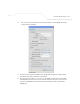
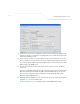
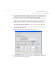
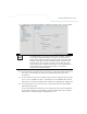
Table Of Contents
- Introduction
- 1.1 New Features
- 1.2 Feature Overview
- 1.2.1 Single or Dual Mode Radio Options
- 1.2.2 Separate LAN and WAN Ports
- 1.2.3 Multiple Mounting Options
- 1.2.4 Antenna Support for 2.4 GHz and 5.2 GHz Radios
- 1.2.5 Sixteen Configurable WLANs
- 1.2.6 Support for 4 BSSIDs per Radio
- 1.2.7 Quality of Service (QoS) Support
- 1.2.8 Industry Leading Data Security
- 1.2.9 VLAN Support
- 1.2.10 Multiple Management Accessibility Options
- 1.2.11 Updatable Firmware
- 1.2.12 Programmable SNMP v1/v2/v3 Trap Support
- 1.2.13 Power-over-Ethernet Support
- 1.2.14 MU-MU Transmission Disallow
- 1.2.15 Voice Prioritization
- 1.2.16 Support for CAM and PSP MUs
- 1.2.17 Statistical Displays
- 1.2.18 Transmit Power Control
- 1.2.19 Advanced Event Logging Capability
- 1.2.20 Configuration File Import/Export Functionality
- 1.2.21 Default Configuration Restoration
- 1.2.22 DHCP Support
- 1.2.23 Multi-Function LEDs
- 1.3 Theory of Operations
- Hardware Installation
- Getting Started
- System Configuration
- Network Management
- Configuring Access Point Security
- 6.1 Configuring Security Options
- 6.2 Setting Passwords
- 6.3 Enabling Authentication and Encryption Schemes
- 6.4 Configuring Kerberos Authentication
- 6.5 Configuring 802.1x EAP Authentication
- 6.6 Configuring WEP Encryption
- 6.7 Configuring KeyGuard Encryption
- 6.8 Configuring WPA Using TKIP
- 6.9 Configuring WPA2-CCMP (802.11i)
- 6.10 Configuring Firewall Settings
- 6.11 Configuring VPN Tunnels
- 6.12 Configuring Content Filtering Settings
- 6.13 Configuring Rogue AP Detection
- 6.14 Configuring User Authentication
- Monitoring Statistics
- Command Line Interface Reference
- Configuring Mesh Networking
- Technical Specifications
- Usage Scenarios
- Customer Support
- Index
Configuring Mesh Networking
9-29
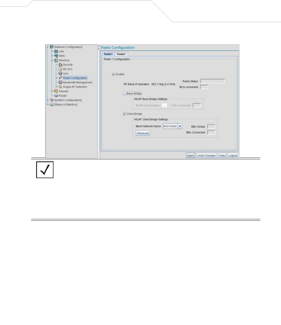
37. For AP2, the IT Team enables both Radio 1 and Radio 2 and defines radio 1 as a client bridge.
38. The IT Team leaves each radio’s Max # Client Bridge setting at the default setting of 12.
This ensures as client bridges are added to the growing mesh network they can be
accounted for.
39. For AP1 and AP2, the IT Team uses the Mesh Network Name drop-down menu to assign
the “trion mesh” WLAN to the radio 1 client bridge. This is the WLAN the AP1 and AP2
radios will use to interoperate with the mesh network devices populating the shipping yard.
40. The IT Team decides to not select the Advanced button within the AP1 and AP2 WLAP
Client Bridge Settings field.
For the next six months, Trion Enterprises’ mesh network only consists of AP1 and AP2. AP1
has already been defined as the root bridge in the mesh network when it was assigned a
Priority value of 1 within the Bridge STP Configuration screen.
NOTE The Trion IT team is aware it is not a good idea to dedicate both radios (of
a dual-radio model access point) to support mesh networking. They know
it is possible to dedicate both radios of a single access point for mesh
support, but the Trion team wants to dedicate the 802.11b/g radio for MU
operation and the 802.11a radio for backhaul support. For AP2, the Trion
team will create two connections to AP1 (one over the 802.11b/g radio
and one over the 802.11a radio). The connection used for forwarding data
for AP2 will be the 802.11b/g radio and the 802.11a radio will be
dedicated for client bridge backhaul.