
User Manual Part 3
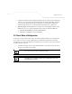
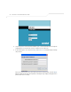
Table Of Contents
- Introduction
- 1.1 New Features
- 1.2 Feature Overview
- 1.2.1 Single or Dual Mode Radio Options
- 1.2.2 Separate LAN and WAN Ports
- 1.2.3 Multiple Mounting Options
- 1.2.4 Antenna Support for 2.4 GHz and 5.2 GHz Radios
- 1.2.5 Sixteen Configurable WLANs
- 1.2.6 Support for 4 BSSIDs per Radio
- 1.2.7 Quality of Service (QoS) Support
- 1.2.8 Industry Leading Data Security
- 1.2.9 VLAN Support
- 1.2.10 Multiple Management Accessibility Options
- 1.2.11 Updatable Firmware
- 1.2.12 Programmable SNMP v1/v2/v3 Trap Support
- 1.2.13 Power-over-Ethernet Support
- 1.2.14 MU-MU Transmission Disallow
- 1.2.15 Voice Prioritization
- 1.2.16 Support for CAM and PSP MUs
- 1.2.17 Statistical Displays
- 1.2.18 Transmit Power Control
- 1.2.19 Advanced Event Logging Capability
- 1.2.20 Configuration File Import/Export Functionality
- 1.2.21 Default Configuration Restoration
- 1.2.22 DHCP Support
- 1.2.23 Multi-Function LEDs
- 1.3 Theory of Operations
- Hardware Installation
- Getting Started
- System Configuration

Getting Started
The access point should be installed in an area tested for radio coverage using one of the site survey
tools available to the Symbol field service technician. Once an installation site has been identified,
the installer should carefully follow the hardware precautions, requirements, mounting guidelines
and power options outlined in Appendix 2, Hardware Installation on page 2-1.
See the following sections for more details:
• Installing the Access Point
• Configuration Options
• Basic Device Configuration
3.1 Installing the Access Point
Make the required cable and power connections before mounting the access point in its final
operating position. Test the access point with an associated MU before mounting and securing the
access point. Carefully follow the mounting instructions in one of the following sections to ensure the
access point is installed correctly: