
User Manual Part 3
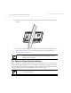
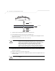
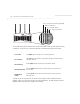
Table Of Contents
- Introduction
- 1.1 New Features
- 1.2 Feature Overview
- 1.2.1 Single or Dual Mode Radio Options
- 1.2.2 Separate LAN and WAN Ports
- 1.2.3 Multiple Mounting Options
- 1.2.4 Antenna Support for 2.4 GHz and 5.2 GHz Radios
- 1.2.5 Sixteen Configurable WLANs
- 1.2.6 Support for 4 BSSIDs per Radio
- 1.2.7 Quality of Service (QoS) Support
- 1.2.8 Industry Leading Data Security
- 1.2.9 VLAN Support
- 1.2.10 Multiple Management Accessibility Options
- 1.2.11 Updatable Firmware
- 1.2.12 Programmable SNMP v1/v2/v3 Trap Support
- 1.2.13 Power-over-Ethernet Support
- 1.2.14 MU-MU Transmission Disallow
- 1.2.15 Voice Prioritization
- 1.2.16 Support for CAM and PSP MUs
- 1.2.17 Statistical Displays
- 1.2.18 Transmit Power Control
- 1.2.19 Advanced Event Logging Capability
- 1.2.20 Configuration File Import/Export Functionality
- 1.2.21 Default Configuration Restoration
- 1.2.22 DHCP Support
- 1.2.23 Multi-Function LEDs
- 1.3 Theory of Operations
- Hardware Installation
- Getting Started
- System Configuration

AP-51xx Access Point Product Reference Guide
2-24
2.9.2 AP-5181 Wall Monuted Installations
Complete the following steps to mount the AP-5181 to a wall using the supplied wall-mounting
bracket:
1. Attach the bracket to a wall with flat side flush against the wall (see the illustration below).
Position the bracket in the intended location and mark the positions of the four mounting
screw holes.
2. Drill four holes in the wall that match the screws and wall plugs.
3. Secure the bracket to the wall.
4. Attach the square mounting plate to the bridge with the supplied screws. Attach the bridge
to the plate on the pole.
5. Use the included nuts to tightly secure the wireless bridge to the bracket.
NOTE The AP-5181 tilt angle may need to be adjusted during the antenna
alignment process. Verify the antenna polarization angle when installing,
enusre the antennas are oriented corretly in respect to the AP-5181's
coverage area.