
User Manual Part 3
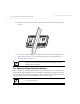
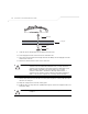
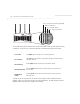
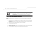
Table Of Contents
- Introduction
- 1.1 New Features
- 1.2 Feature Overview
- 1.2.1 Single or Dual Mode Radio Options
- 1.2.2 Separate LAN and WAN Ports
- 1.2.3 Multiple Mounting Options
- 1.2.4 Antenna Support for 2.4 GHz and 5.2 GHz Radios
- 1.2.5 Sixteen Configurable WLANs
- 1.2.6 Support for 4 BSSIDs per Radio
- 1.2.7 Quality of Service (QoS) Support
- 1.2.8 Industry Leading Data Security
- 1.2.9 VLAN Support
- 1.2.10 Multiple Management Accessibility Options
- 1.2.11 Updatable Firmware
- 1.2.12 Programmable SNMP v1/v2/v3 Trap Support
- 1.2.13 Power-over-Ethernet Support
- 1.2.14 MU-MU Transmission Disallow
- 1.2.15 Voice Prioritization
- 1.2.16 Support for CAM and PSP MUs
- 1.2.17 Statistical Displays
- 1.2.18 Transmit Power Control
- 1.2.19 Advanced Event Logging Capability
- 1.2.20 Configuration File Import/Export Functionality
- 1.2.21 Default Configuration Restoration
- 1.2.22 DHCP Support
- 1.2.23 Multi-Function LEDs
- 1.3 Theory of Operations
- Hardware Installation
- Getting Started
- System Configuration

Hardware Installation
2-23
2.9 Mounting the AP-5181
The AP-5181 can be connected to a pole or attach to a wall. Choose one of the following mounting
options based on the physical environment of the coverage area. Do not mount the AP-5181 in a
location that has not been approved in a site survey.
Refer to the following, depending on how you intend to mount the AP-5181:
• AP-5181 Pole Mounted Installations
• AP-5181 Wall Monuted Installations
2.9.1 AP-5181 Pole Mounted Installations
Complete the following steps to mount the AP-5181 to a 1.5 to 2 inch diameter steel pole or tube
(using the mounting bracket):
1. Fit the edges of the V-shaped clamp parts into the slots on the flat side of the rectangular
plate. The inner slots are for the 1.5-inch diameter pole and the outer slots for a 2-inch
diameter pole.
2. Place the V-shaped bracket clamp parts around the pole and tighten the nuts just enough to
hold the bracket to the pole. (The bracket may need to be rotated around the pole during the
antenna alignment process).
3. Attach the square mounting plate to the bridge with the supplied screws.
4. Attach the AP-5181 and mounting plate to the bracket already fixed to the pole.
5. Secure the AP-5181 to the pole bracket using the provided nuts.
Boot and Power Status
Solid white indicates the AP-5131 is adequately powered.
Error Conditions
Solid red indicates the AP-5131 is experiencing a problem condition requiring
immediate attention.
Power and Error
Conditions
Blinking red indicates the AP-5131 Rogue AP Detection feature has located a
rogue device