
User Manual Part 3
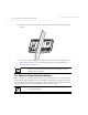
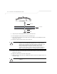
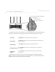
Table Of Contents
- Introduction
- 1.1 New Features
- 1.2 Feature Overview
- 1.2.1 Single or Dual Mode Radio Options
- 1.2.2 Separate LAN and WAN Ports
- 1.2.3 Multiple Mounting Options
- 1.2.4 Antenna Support for 2.4 GHz and 5.2 GHz Radios
- 1.2.5 Sixteen Configurable WLANs
- 1.2.6 Support for 4 BSSIDs per Radio
- 1.2.7 Quality of Service (QoS) Support
- 1.2.8 Industry Leading Data Security
- 1.2.9 VLAN Support
- 1.2.10 Multiple Management Accessibility Options
- 1.2.11 Updatable Firmware
- 1.2.12 Programmable SNMP v1/v2/v3 Trap Support
- 1.2.13 Power-over-Ethernet Support
- 1.2.14 MU-MU Transmission Disallow
- 1.2.15 Voice Prioritization
- 1.2.16 Support for CAM and PSP MUs
- 1.2.17 Statistical Displays
- 1.2.18 Transmit Power Control
- 1.2.19 Advanced Event Logging Capability
- 1.2.20 Configuration File Import/Export Functionality
- 1.2.21 Default Configuration Restoration
- 1.2.22 DHCP Support
- 1.2.23 Multi-Function LEDs
- 1.3 Theory of Operations
- Hardware Installation
- Getting Started
- System Configuration

Hardware Installation
2-21
For Symbol power injector installations:
a. Connect a RJ-45 Ethernet cable between the network data supply (host) and the Power
Injector Data In connector.
b. Connect a RJ-45 Ethernet cable between the power injector Data & Power Out
connector and the AP-5131 LAN port.
c. Ensure the cable length from the Ethernet source (host) to the power injector and
AP-5131 does not exceed 100 meters (333 ft). The power injector has no On/Off power
switch. The power injector receives power as soon as AC power is applied. For more
information on using the power injector, see Symbol Power Injector System on page 2-9.
For standard Symbol 48-Volt Power Adapter (Part No. 50-24000-050) and line cord
installations:
a. Connect RJ-45 Ethernet cable between the network data supply (host) and the AP-5131
LAN port.
b. Verify the power adapter is correctly rated according the country of operation.
c. Connect the power supply line cord to the power adapter.
d. Attach the power adapter cable into the power connector on the AP-5131.
e. Plug the power adapter into an outlet.
16. Verify the behavior of the AP-5131 LED lightpipe. For more information, see AP-5131 LED
Indicators on page 2-21.
17. Place the ceiling tile back in its frame and verify it is secure.
The AP-5131 is ready to configure. For information on an AP-5131 default configuration, see
Getting Started on page 3-1. For specific details on AP-5131 system configurations, see
System Configuration on page 4-1.
2.8 AP-5131 LED Indicators
The AP-5131 utilizes seven LED indicators. Five LEDs display within four LED slots on the front of the
AP-5131 (on top of the AP-5131 housing) and two LEDs (for above the ceiling installations) are located
on the back of the device (the side containing the LAN, WAN and antenna connectors).