
User Manual Part 3
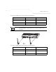
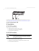
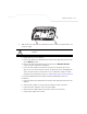
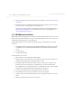
Table Of Contents
- Introduction
- 1.1 New Features
- 1.2 Feature Overview
- 1.2.1 Single or Dual Mode Radio Options
- 1.2.2 Separate LAN and WAN Ports
- 1.2.3 Multiple Mounting Options
- 1.2.4 Antenna Support for 2.4 GHz and 5.2 GHz Radios
- 1.2.5 Sixteen Configurable WLANs
- 1.2.6 Support for 4 BSSIDs per Radio
- 1.2.7 Quality of Service (QoS) Support
- 1.2.8 Industry Leading Data Security
- 1.2.9 VLAN Support
- 1.2.10 Multiple Management Accessibility Options
- 1.2.11 Updatable Firmware
- 1.2.12 Programmable SNMP v1/v2/v3 Trap Support
- 1.2.13 Power-over-Ethernet Support
- 1.2.14 MU-MU Transmission Disallow
- 1.2.15 Voice Prioritization
- 1.2.16 Support for CAM and PSP MUs
- 1.2.17 Statistical Displays
- 1.2.18 Transmit Power Control
- 1.2.19 Advanced Event Logging Capability
- 1.2.20 Configuration File Import/Export Functionality
- 1.2.21 Default Configuration Restoration
- 1.2.22 DHCP Support
- 1.2.23 Multi-Function LEDs
- 1.3 Theory of Operations
- Hardware Installation
- Getting Started
- System Configuration

AP-51xx Access Point Product Reference Guide
2-16
e. Plug the power adapter into an outlet.
9. Verify the behavior of the AP-5131 LEDs. For more information, see AP-5131 LED Indicators
on page 2-21.
The AP-5131 is ready to configure. For information on an AP-5131 default configuration, see
Getting Started on page 3-1. For specific details on AP-5131 system configurations, see
System Configuration on page 4-1.
2.7.3 Suspended Ceiling T-Bar Installations
A suspended ceiling mount requires holding the AP-5131 up against the T-bar of a suspended ceiling
grid and twisting the AP-5131 chassis onto the T-bar.
The mounting hardware and tools (customer provided) required to install the AP-5131 on a ceiling T-
bar consists of:
• Safety wire (recommended)
• Security cable (optional)
To install the AP-5131 on a ceiling T-bar:
1. If required, loop a safety wire —with a diameter of at least 1.01 mm (.04 in.), but no more
than 0.158 mm (.0625 in.) —through the tie post (above the AP-5131’s console connector)
and secure the loop.
2. If required, install and attach a security cable to the AP-5131 lock port.
3. Attach the radio antennae to their correct connectors.
NOTE If the AP-5131 is utilizing remote management antennae, a wire cover
can be used to provide a clean finished look to the installation. Contact
Symbol for more information.
CAUTION Both the Dual and Single Radio model AP-5131s use RSMA type
antenna connectors. On the Dual Radio AP-5131, a single dot on the
antenna connector indicates the primary antenna for both Radio 1 (2.4
GHz) and Radio 2 (5.2 GHz). Two dots designate the secondary
antenna for both Radio 1 and Radio 2. On Single Radio models, a
single dot on the antenna connector indicates the primary antenna for
Radio 1, and two dots designate the secondary antenna for Radio 1
!