
User Manual Part 3
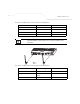
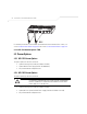
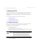
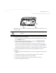
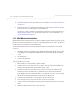
Table Of Contents
- Introduction
- 1.1 New Features
- 1.2 Feature Overview
- 1.2.1 Single or Dual Mode Radio Options
- 1.2.2 Separate LAN and WAN Ports
- 1.2.3 Multiple Mounting Options
- 1.2.4 Antenna Support for 2.4 GHz and 5.2 GHz Radios
- 1.2.5 Sixteen Configurable WLANs
- 1.2.6 Support for 4 BSSIDs per Radio
- 1.2.7 Quality of Service (QoS) Support
- 1.2.8 Industry Leading Data Security
- 1.2.9 VLAN Support
- 1.2.10 Multiple Management Accessibility Options
- 1.2.11 Updatable Firmware
- 1.2.12 Programmable SNMP v1/v2/v3 Trap Support
- 1.2.13 Power-over-Ethernet Support
- 1.2.14 MU-MU Transmission Disallow
- 1.2.15 Voice Prioritization
- 1.2.16 Support for CAM and PSP MUs
- 1.2.17 Statistical Displays
- 1.2.18 Transmit Power Control
- 1.2.19 Advanced Event Logging Capability
- 1.2.20 Configuration File Import/Export Functionality
- 1.2.21 Default Configuration Restoration
- 1.2.22 DHCP Support
- 1.2.23 Multi-Function LEDs
- 1.3 Theory of Operations
- Hardware Installation
- Getting Started
- System Configuration

AP-51xx Access Point Product Reference Guide
2-14
5. Verify the behavior of the AP-5131 LEDs. For more information, see AP-5131 LED Indicators
on page 2-21.
6. Return the AP-5131 to an upright position and place it in the location you wish it to operate.
Ensure the AP-5131 is sitting evenly on all four rubber feet.
The AP-5131 is ready to configure. For information on an AP-5131 default configuration, see
Getting Started on page 3-1. For specific details on AP-5131 system configurations, see
System Configuration on page 4-1.
2.7.2 Wall Mounted Installations
Wall mounting requires hanging the AP-5131 along its width (or length) using the pair of slots on the
bottom of the unit and using the AP-5131 itself as a mounting template for the screws. The AP-5131
can be mounted onto any plaster or wood wall surface.
The mounting hardware and tools (customer provided) required to install the AP-5131 on a wall
consists of:
• Two Phillips pan head self-tapping screws (ANSI Standard) #6-18 X 0.875in. Type A or AB
Self-Tapping screw, or (ANSI Standard Metric) M3.5 X 0.6 X 20mm Type D Self-Tapping
screw
• Two wall anchors
• Security cable (optional)
To mount the AP-5131 on a wall:
1. Orient the AP-5131 on the wall by its width or length.
2. Using the arrows on one edge of the case as guides, move the edge to the midline of the
mounting area and mark points on the midline for the screws.
3. At each point, drill a hole in the wall, insert an anchor, screw into the anchor the wall
mounting screw and stop when there is 1mm between the screw head and the wall.
If pre-drilling a hole, the recommended hole size is 2.8mm (0.11in.) if the screws are going
directly into the wall and 6mm (0.23in.) if wall anchors are being used.
4. If required, install and attach a security cable to the AP-5131 lock port.
5. Place the large corner of each of the mount slots over the screw heads.
6. Slide the AP-5131 down along the mounting surface to hang the mount slots on the screw
heads.
7. Attach the radio antennae to their correct connectors.