
User Manual Part 3
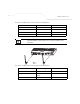
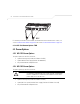
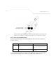
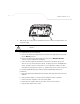
Table Of Contents
- Introduction
- 1.1 New Features
- 1.2 Feature Overview
- 1.2.1 Single or Dual Mode Radio Options
- 1.2.2 Separate LAN and WAN Ports
- 1.2.3 Multiple Mounting Options
- 1.2.4 Antenna Support for 2.4 GHz and 5.2 GHz Radios
- 1.2.5 Sixteen Configurable WLANs
- 1.2.6 Support for 4 BSSIDs per Radio
- 1.2.7 Quality of Service (QoS) Support
- 1.2.8 Industry Leading Data Security
- 1.2.9 VLAN Support
- 1.2.10 Multiple Management Accessibility Options
- 1.2.11 Updatable Firmware
- 1.2.12 Programmable SNMP v1/v2/v3 Trap Support
- 1.2.13 Power-over-Ethernet Support
- 1.2.14 MU-MU Transmission Disallow
- 1.2.15 Voice Prioritization
- 1.2.16 Support for CAM and PSP MUs
- 1.2.17 Statistical Displays
- 1.2.18 Transmit Power Control
- 1.2.19 Advanced Event Logging Capability
- 1.2.20 Configuration File Import/Export Functionality
- 1.2.21 Default Configuration Restoration
- 1.2.22 DHCP Support
- 1.2.23 Multi-Function LEDs
- 1.3 Theory of Operations
- Hardware Installation
- Getting Started
- System Configuration

AP-51xx Access Point Product Reference Guide
2-12
2.7 Mounting the AP-5131
The AP-5131 can rest on a flat surface, attach to a wall, mount under a suspended T-Bar or above a
ceiling (plenum or attic). Choose one of the following mounting options based on the physical
environment of the coverage area. Do not mount the AP-5131 in a location that has not been approved
in a site survey.
Refer to the following, depending on how you intend to mount the AP-5131:
• Desk Mounted Installations
• Wall Mounted Installations
• Suspended Ceiling T-Bar Installations
• Above the Ceiling (Plenum) Installations
2.7.1 Desk Mounted Installations
The desk mount option uses rubber feet allowing the unit to sit on most flat surfaces. The four (4)
round rubber feet can be found in the AP-5131 (main) box in a separate plastic bag.
To install the AP-5131 in a desk mount orientation:
1. Turn the AP-5131 upside down.
2. Attach the radio antennae to their correct connectors.
The antenna protection plate cannot be used in a desk mount configuration, as the plate only
allows antennas to be positioned in a downward orientation.
3. Remove the backings from the four (4) rubber feet and attach them to the four rubber feet
recess areas on the AP-5131.
CAUTION Both the Dual and Single Radio model AP-5131’s use RSMA type
antenna connectors. On the Dual Radio AP-5131, a single dot on the
antenna connector indicates the primary antenna for both Radio 1 (2.4
GHz) and Radio 2 (5.2 GHz). Two dots designate the secondary
antenna for both Radio 1 and Radio 2. On Single Radio models, a
single dot on the antenna connector indicates the primary antenna for
Radio 1, and two dots designate the secondary antenna for Radio 1.
!