
User Manual Part 3
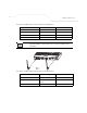
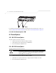
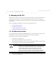
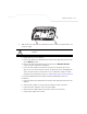
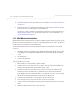
Table Of Contents
- Introduction
- 1.1 New Features
- 1.2 Feature Overview
- 1.2.1 Single or Dual Mode Radio Options
- 1.2.2 Separate LAN and WAN Ports
- 1.2.3 Multiple Mounting Options
- 1.2.4 Antenna Support for 2.4 GHz and 5.2 GHz Radios
- 1.2.5 Sixteen Configurable WLANs
- 1.2.6 Support for 4 BSSIDs per Radio
- 1.2.7 Quality of Service (QoS) Support
- 1.2.8 Industry Leading Data Security
- 1.2.9 VLAN Support
- 1.2.10 Multiple Management Accessibility Options
- 1.2.11 Updatable Firmware
- 1.2.12 Programmable SNMP v1/v2/v3 Trap Support
- 1.2.13 Power-over-Ethernet Support
- 1.2.14 MU-MU Transmission Disallow
- 1.2.15 Voice Prioritization
- 1.2.16 Support for CAM and PSP MUs
- 1.2.17 Statistical Displays
- 1.2.18 Transmit Power Control
- 1.2.19 Advanced Event Logging Capability
- 1.2.20 Configuration File Import/Export Functionality
- 1.2.21 Default Configuration Restoration
- 1.2.22 DHCP Support
- 1.2.23 Multi-Function LEDs
- 1.3 Theory of Operations
- Hardware Installation
- Getting Started
- System Configuration

Hardware Installation
2-11
The power injector has no On/Off power switch. The power injector receives power and is
ready for access point device connection and operation as soon as AC power is applied.
2.6.1.3 Power Injector LED Indicators
The power injector demonstrates the following LED behavior under normal and/or problematic
operating conditions:
For more information and device specifications for the Symbol power injector, refer to the Power
Injector Quick Install Guide (Part No. 72-70762-01) available from the Symbol Web site.
LED AC (Main) Port
Green (Steady) Power injector is receiving power from AC
outlet.
Indicates a device is connected to the
power injector’s outgoing Data & Power
cable.
Green (Blinking) Output voltage source is out of range. The power injector is overloaded or has a
short circuit.