
User Manual Part 3
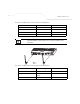
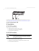
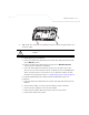
Table Of Contents
- Introduction
- 1.1 New Features
- 1.2 Feature Overview
- 1.2.1 Single or Dual Mode Radio Options
- 1.2.2 Separate LAN and WAN Ports
- 1.2.3 Multiple Mounting Options
- 1.2.4 Antenna Support for 2.4 GHz and 5.2 GHz Radios
- 1.2.5 Sixteen Configurable WLANs
- 1.2.6 Support for 4 BSSIDs per Radio
- 1.2.7 Quality of Service (QoS) Support
- 1.2.8 Industry Leading Data Security
- 1.2.9 VLAN Support
- 1.2.10 Multiple Management Accessibility Options
- 1.2.11 Updatable Firmware
- 1.2.12 Programmable SNMP v1/v2/v3 Trap Support
- 1.2.13 Power-over-Ethernet Support
- 1.2.14 MU-MU Transmission Disallow
- 1.2.15 Voice Prioritization
- 1.2.16 Support for CAM and PSP MUs
- 1.2.17 Statistical Displays
- 1.2.18 Transmit Power Control
- 1.2.19 Advanced Event Logging Capability
- 1.2.20 Configuration File Import/Export Functionality
- 1.2.21 Default Configuration Restoration
- 1.2.22 DHCP Support
- 1.2.23 Multi-Function LEDs
- 1.3 Theory of Operations
- Hardware Installation
- Getting Started
- System Configuration

AP-51xx Access Point Product Reference Guide
2-10
2.6.1.1 Preparing for Site Installation
The power injector can be installed free standing, on an even horizontal surface or wall mounted
using the power injector’s wall mounting key holes. The following guidelines should be adhered to
before cabling the power injector to an Ethernet source and an access point:
• Do not block or cover airflow to the power injector.
• Keep the power injector away from excessive heat, humidity, vibration and dust.
• The power injector is not a repeater, and does not amplify the Ethernet data signal. For
optimal performance, ensure the power injector is placed as close as possible to the
network data port.
2.6.1.2 Cabling the Power Injector
To install the power injector to an Ethernet data source and access point:
1. Connect the power injector to an AC outlet (110VAC to 220VAC).
2. Connect an RJ-45 Ethernet cable between the network data supply (host) and the power
injector Data In connector.
3. Connect an RJ-45 Ethernet cable between the power injector Data & Power Out connector
and the Symbol access point LAN port.
Ensure the cable length from the Ethernet source (host) to the power injector and access
point does not exceed 100 meters (333 ft.)
CAUTION Ensure AC power is supplied to the power injector using an AC cable
with an appropriate ground connection approved for the country of
operation.
CAUTION Cabling the power injector to the access point’s WAN port renders the
AP-5131 non-operational. Only use a AP-PSBIAS-1P2-AFR model
power injector with the access point’s LAN port.
!
!